paloking
Newbie level 1
How do i design a schematic for Counter with Reset/Pause on FPGA
Hey All!
Currently struggling a tonne getting my mind around designing basic schematics on an FPGA (Device is a Cyclone IV E EP4CE6E228). Basically the schematic is supposed to make a digit move across 3 of the 4 7-segment displays (with an indicator of direction on the 4th). Out of the 4 buttons avaible 1 needs to be a Reset/1 needs to be a Pause and the remaining 2 for selecting Frequency. I'm honestly really lost at the moment, and can't seem to find much information on making these Schematics (Most tutorials are VHDL coding). I'm using Quartus for this!
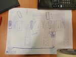
An example High Level Design is attached for reference.
I think i've figured out the Freq. Divider, Freq. Selector, Selection MUX and 7 Segment Decoder.
