Continue to Site

Welcome to EDAboard.com

Welcome to our site! EDAboard.com is an international Electronics Discussion Forum focused on EDA software, circuits, schematics, books, theory, papers, asic, pld, 8051, DSP, Network, RF, Analog Design, PCB, Service Manuals... and a whole lot more! To participate you need to register. Registration is free. Click here to register now.

Coiled resistor in high amperage PSU?

Status
Not open for further replies.

neazoi

Advanced Member level 6
Joined
Jan 5, 2008
Messages
4,119
Helped
13
Reputation
26
Reaction score
15
Trophy points
1,318
Location
Greece
Activity points
36,918
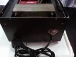
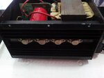
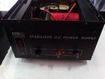
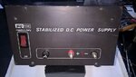
Hi I saw a linear (not switching) PSU of 40A 13.8v.
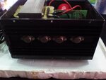
It has eight 2n3055 plus another one, possibly for driving.
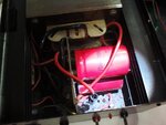
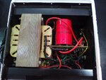
Inside there is no chip but a small circuit composed of transistors, a small plastic one and one like the package of BD139.

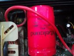
However, inside, there is a coil-shaped resistor (I believe it is a resistor) with air-core (solenoid).
When the PSU draws 20A this resistor gets very hot and hot air comes out of it. It is like the air out of a high wattage soldering iron, when it is heated the hot air quickly goes up.

What is this resistor used for and why it gets so hot in high load?
Next question is, can I replace it with a "brick" type one and fix it to the heatsink? But how should I measure it's value hot or cold?
 

Intriguing! And I mean it!

But without good photos, or PSU brand or model name, or any additional info, it is very hard to guess.
 

Intriguing! And I mean it!

But without good photos, or PSU brand or model name, or any additional info, it is very hard to guess.

Here it is.
The coiled resistor is shown in the last photo (7.jpg) on the very right
 

Attachments

  • 7.jpg
    7.jpg
    59.8 KB · Views: 119
  • 8.jpg
    8.jpg
    67.3 KB · Views: 108
  • 6.jpg
    6.jpg
    57.7 KB · Views: 124
  • 5.jpg
    5.jpg
    61.9 KB · Views: 133
  • 4.jpg
    4.jpg
    60.3 KB · Views: 122
  • 3.jpg
    3.jpg
    57.5 KB · Views: 132
  • 2.jpg
    2.jpg
    94.5 KB · Views: 122
  • 1.jpg
    1.jpg
    56 KB · Views: 124

I think this may just be iron wire used as the current sense
resistor, with the lack of body providing better air cooling
-throw than a solid body type would. Given that even this
one gets toasty, a solid body one would probably fry or
*****.

^^^^^ that was a perfectly good English word used
appropriately - c,r,a,c,k. Mods, can you train the censor
to accept real words from the dictionary?


I see iron wire used as the sensing resistor in cheap DMMs
I have, on the 10A jack.

so is it used on current limiting mechanism?
If I put a fan inside the enclosure will this interfere with the operation of the resistor?
 

It is unlikely to be iron wire (iron has a high temp coefficient) but rather nichrome. They too get attracted by a magnet and many people think they are the same. It is also possible to have manganin or constantan wires in the similar configuration (but nichrome is considerably cheaper option).

The position seen in the photo allows for best cooling you can get (you do not need a fan). Soldering nichrome can be tricky and the way the red wire is connected is, to say the least, is hopeless.

You can measure the resistance when cold but I am not sure about the role of this resistor. At 40A it will have considerable inductance (effect) and it may have to stabilization role too.
 

As far I'm aware of, Nichrome resistance wire (Ni80Cr20) is non-magnetic. If the wire isn't galvanically plated, you need special flux to soft solder it. Either diluted phosphoric acid or dedicated stainless steel solder. Chromium oxide makes the trouble, other resistance wire materials like Manganin or Constantan or better solderable.
 

It is unlikely to be iron wire (iron has a high temp coefficient) but rather nichrome. They too get attracted by a magnet and many people think they are the same. It is also possible to have manganin or constantan wires in the similar configuration (but nichrome is considerably cheaper option).

The position seen in the photo allows for best cooling you can get (you do not need a fan). Soldering nichrome can be tricky and the way the red wire is connected is, to say the least, is hopeless.

You can measure the resistance when cold but I am not sure about the role of this resistor. At 40A it will have considerable inductance (effect) and it may have to stabilization role too.

Drawing 20A makes the 40A fan-less PSU het hot after a while, not because of the heat in the 2n3055 but mainly because of the resistor. In this fanless configuration and with this tight-space enclosure everything gets hot after a while even the transformer. I guess that is why the enclosure is all metal-made

I opened the cover and installed a small slow-rpm fan in it. I do not like fans but things get really cool even with this small air flow.

The resistor is not soldered, clips are attached to it which are then soldered to the PCB, but the resistor itself is not soldered. And you are right, it is placed between the two drilled places (top and bottom) of the enclosure so as to get cooled.
 

Status
Not open for further replies.

Similar threads

Part and Inventory Search

Welcome to EDABoard.com

Sponsor

Back
Top