Continue to Site

Welcome to EDAboard.com

Welcome to our site! EDAboard.com is an international Electronics Discussion Forum focused on EDA software, circuits, schematics, books, theory, papers, asic, pld, 8051, DSP, Network, RF, Analog Design, PCB, Service Manuals... and a whole lot more! To participate you need to register. Registration is free. Click here to register now.

How do I reduce the speed of a 12v children's car?

Status
Not open for further replies.
Re: how do i reduce the speed of a 12v childrens car

yes i have a voltmeter and can work that out
 

Re: how do i reduce the speed of a 12v childrens car

Good!
What you need to do is work out which wire is which. At the speed control, measure the voltage from each wire to each other wire. What you are trying to find out is which two have a steady voltage on them and which has the voltage that varies with the pedal position. Of the two steady ones (there might be a slight fluctuation as the pedal is pushed but it should be fairly small) you need to finds out which is the more negative voltage. Then, with the negative meter probe (usually black) on that wire and positive probe (usually red) on the wire that changes with pedal position, read the voltage at 'stop' and at maximum speed. I advise you not do this while the car is in motion unless you can run fast! Let me know the two voltages.

It would also be a great help if you could unplug the wires from the control and use the meter to measure resistance (Ohms) across the points ON THE CONTROL the two fixed voltage wires went to. You can probably do this from the socket the wires were plugged into. I would expect the resistance to be somewhere between about 1000 Ohms (1K) and 100,000 Ohms (100K) to give you some confidence you have the right connections. Don't worry about the contact the varying voltage wire went to as it will change value as the pedal is moved anyway. The resistance across the fixed voltage points will effectively be the value of the control and from that and the voltage you measured we can work out a suitable addition to limit the speed.

Good Luck.

Brian.

hi i am slightly confused re measuring the ohms- am i measuring the controller side or the resistor side once unplugged?
 

Re: how do i reduce the speed of a 12v childrens car

Voltages with the plug inserted, as though it was in normal operation.
Ohms across the resistor only with the plug removed. Don't try to measure resistance with the plug inserted as the meter could be damaged.

Brian.
 

Re: how do i reduce the speed of a 12v childrens car

ok so been playing with the voltmeter- the is what i found- the resistor has three wires (red yellow and green) and my voltmeter black and red- this is what i found in the various combinations (vm= voltmeter and r= ressistor end-

1) red (vm) connected to red (r) plus black (vm) connected to yellow (r) = constant 4.35v

2) black (vm) connected to green (r) plus red (vm) connected to red (r)= +3.49v and reduces to 0.767v when accelerator fully depressed

3) black (vm) connected to yellow (r) plus red (vm) connected to green (r)= +0.867 and rises to 3.59v when accelerator fully depressed


as for the ohms- i disconnected the accelerator resistor and tested the control unit side. the only combination i could get a reading was-

1) black (vm) to green plus red (vm) to yellow = 97.5
2) red (vm) to green pus black (vm) to yellow= 100

i hope this makes some sense as i cant work it out!
 

Re: how do i reduce the speed of a 12v childrens car

Sorry for all the delays - I'm working with one eye in the Forum and the other on something else.

Great, it looks like the positive voltage is the red wire, negative is the yellow wire and the control voltage is on the green wire. Progress!

As the voltage increases as the pedal is pressed, it implies an increasing voltage produces more speed, we need to limit the voltage on the red wire to prevent it going so high.

The Ohms measurement is wrong though, you did it from the cable looking into the electronics, I need it the other way around so you measure across the variable resistor. If you note where the yellow and red wires connect to the variable resistor and, with it disconnected from the control box, measure the Ohms across those points it will give the value of the resistor. It should measure the same if you reverse the meter probes and it shouldn't vary if the pedal is pressed.

Brian.
 

Re: how do i reduce the speed of a 12v childrens car

As you are now inside the component level identification , it will be better if you attach a closeup photo of the accelerator pedal resistor with wires .
 

Re: how do i reduce the speed of a 12v childrens car

As you are now inside the component level identification , it will be better if you attach a closeup photo of the accelerator pedal resistor with wires .

hi, i have attached photos earlier in this thread- thanks

- - - Updated - - -

hi again, so today i connected my voltmeter to the resistor/pedal side. findings were as follows-

1) red (vm) to red (r) plus black (vm) to yellow (r) = 2.42 ohms - did not change if i pressed accelerator

2) red (vm) to red (r) plus black (vm) to green (r) = no reading

3) red (vm) to green (r) plus black (vm) to green or yellow (r) = no reading

4) red (vm) to yellow (r) plus black (vm) to red (r) = 2.41 ohm

5) red (vm) to yellow (r) plus black (vm) to green (r) = no reading


sorry about all this - its a bit like guiding a plane down where the pilot cant fly! much appreciated though!
 

Re: how do i reduce the speed of a 12v childrens car

Hmmm....

Something doesn't look right there. I wonder if there are other components inside the box with the variable resistor. I can understand two of the wires having low resistance between them if it was a standard potentiometer (a variable resistor where both ends of a carbon track and a wiper along it's length are present) because the wiper would be at one end of the track with the control in it's 'relaxed' state but there should be a reading to the other wire regardless.

Also, if the 2.4 Ohms is between the yellow and red wires which we previously measured 4.35V across, it would imply about 2 Amps would flow through it. That would require fairly thick wires and the resistor would run very hot. Does you testmeter have 'autoranging' or does it have a manual resistance range selector? I have a feeling the number may be wrong.

Brian.
 

Re: how do i reduce the speed of a 12v childrens car

Hmmm....

Something doesn't look right there. I wonder if there are other components inside the box with the variable resistor. I can understand two of the wires having low resistance between them if it was a standard potentiometer (a variable resistor where both ends of a carbon track and a wiper along it's length are present) because the wiper would be at one end of the track with the control in it's 'relaxed' state but there should be a reading to the other wire regardless.

Also, if the 2.4 Ohms is between the yellow and red wires which we previously measured 4.35V across, it would imply about 2 Amps would flow through it. That would require fairly thick wires and the resistor would run very hot. Does you testmeter have 'autoranging' or does it have a manual resistance range selector? I have a feeling the number may be wrong.

Brian.
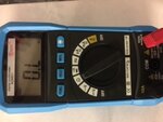
Hi, i am lost when you talk autoranging- its a digital multimeter ADM01 and i set it as per picture image1.JPG
 

Re: how do i reduce the speed of a 12v childrens car

autoranging - the multimeter will automatically select the range of values it displays. There will likely be something like K that shows up if the ohms value is in the Kohm range, or M if in the Mohm range.

It would make more sense if the reading was 2.4Kohms not 2.4ohms...

Try the reading again and see if you have a K somewhere on the display, or better yet take a picture with better resolution while the reading is being taken.
 

Re: how do i reduce the speed of a 12v childrens car

Note that if that picture is taken as you read the resistance, you have the black probe in the wrong socket on the meter. Black should go in the 'COM' (common) hole, the red one is correct

I agree with ads-ee, a more reasonable reading would be 2.4K. If we are right, it's time to buy a pre-set variable resistor or potentiometer with a value of about 10K to add to the wiring to limit the speed. Ignoring current flowing into the control box, which would be difficult to measure, that would give an adjustment range of full to about 20% of the present maximum speed.

Brian.
 

Re: how do i reduce the speed of a 12v childrens car

Hmmm....

Something doesn't look right there. I wonder if there are other components inside the box with the variable resistor. I can understand two of the wires having low resistance between them if it was a standard potentiometer (a variable resistor where both ends of a carbon track and a wiper along it's length are present) because the wiper would be at one end of the track with the control in it's 'relaxed' state but there should be a reading to the other wire regardless.

Also, if the 2.4 Ohms is between the yellow and red wires which we previously measured 4.35V across, it would imply about 2 Amps would flow through it. That would require fairly thick wires and the resistor would run very hot. Does you testmeter have 'autoranging' or does it have a manual resistance range selector? I have a feeling the number may be wrong.

Brian.
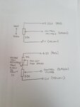
image1.JPG

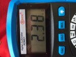
good morning- i retested with my voltmeter and got the same ohms reading at 2.38 but this time noticed it has a little 'k' by the 2.38 - i hope this explains things
 

Re: how do i reduce the speed of a 12v childrens car

Now it makes sense, a factor of 1,000 times make a big difference!

This is what is needed:
20180921_120310a.jpg
The top diagram is what you have now, the wiper (middle, arrowed) connection to the potentiometer picks off a proportion of the voltage from along the track (the box). As the pedal is pressed, it physically moves the wiper toward the top of the track where it picks up a higher proportion of the 4.35V and sends it down the green wire.

The bottom diagram shows the added potentiometer. Wiring the wiper to one end just makes it a variable resistor, the position of the wiper changes it's resistance from maximum (10K) to shorted out. Some of the 4.35V is dropped across the variable resistor, the amount depends on the resistance it is set to. If the new resistance is zero you are back to the original circuit, if set to maximum resistance, the green wire can't go above about 1V. Hence, it pre-sets the maximum voltage the pedal can produce.

The new control is easy to wire in, just break the existing red wire and connect it across the cut. Try to position it where it can't easily be reached or your son will soon work out how to beef things up again! The potentiometer you need can be very small, something like these:
https://www.ebay.co.uk/itm/3386F-1-...hash=item2aa4a29aad:m:mqvtXOpe5VoshiI1S_Yoc9w

Brian.
 

Re: how do i reduce the speed of a 12v childrens car

The new control is easy to wire in, just break the existing red wire and connect it across the cut. Try to position it where it can't easily be reached or your son will soon work out how to beef things up again! The potentiometer you need can be very small, something like these:
Brian.

You could also put shrink wrap around the adjustment pot and then it won't be susceptible to the elements (if any can get in there) nor will it be as visible that something can be turned to turbo charge his ride again (if nothing else you'll know if he tampered with it).
 

I'm glad you qualified that statement by saying it should be wrapped around the pot. For one moment I thought you meant to wrap around his son. It works equally well both ways but one is more ethically correct than the other. :)

Brian.
 

Thankyou so would this one work and what value do i need to get? it seems to have a choice of 5 , 10 or 100k. I seem to recall that you mentioned before that it was to go in the green wire so are you sure about the red? please dont take that question the wrong way as i know absolutely nothing about this. i can rebuild a ferrari v12 engine but this little lesson has taught me how little i know about electronics! I found this one on ebay - would it work and what value do i need to get? it seems to have a choice of 5 , 10 or 100k.

**broken link removed**

- - - Updated - - -

just one more thing- i also posted a plea for help on electronics point. To be honest you and only one other chap seemed to make sense and i supplied him with much the same info. This is his last post and i wonder whether you agree with him?-

The resistance measurement is of no interest. The thing you call a "variable resistor" is not a resistor at all. It is an electronic device that takes two power leads in and outputs a voltage dependent on the position of sliding pieces. That voltage is sent to the motor controller and determines the speed of the motor.

From your measurements, the wiring can be deduced to be:

yellow: ground
red: +4.35V
green: variable output

As @kellys_eye says, two resistors making a voltage divider can reduce the range of voltages output on the green wire and sent to the motor controller, which should limit the upper speed. Since it will also lower the lowest voltage out, it might mean there is added dead space when you start to push the accelerator pedal.

Bob
 

That potentiometer should be fine, use 10K value. If you use a smaller value you get less restriction of top speed, use the next value up (100K) and will restrict it far too much, in fact it may not move at all.
The resistance measurement is of no interest. The thing you call a "variable resistor" is not a resistor at all. It is an electronic device that takes two power leads in and outputs a voltage dependent on the position of sliding pieces.
That's quite funny, it exactly describes what a potentiometer does! I can almost hear the howls of laughter from other users on here: "that's not the accelerator, it's the pedal to make it go faster" :grin:

The resistance DOES matter, in fact without knowing it the additional resistance to set the speed limit can't be deduced.

It is true that the lower speed will also be reduced but I assume if the pedal isn't pressed at all the car doesn't move so I doubt that would be a problem. If it is, there is another simple fix but don't worry about that yet.

If you buy the potentiometer in the link, you only need two connections, across the cut in the original red wire. Use one of the end tags as one connection and link the middle and other end tag as the other connection.

Brian.
 

That potentiometer should be fine, use 10K value. If you use a smaller value you get less restriction of top speed, use the next value up (100K) and will restrict it far too much, in fact it may not move at all.
That's quite funny, it exactly describes what a potentiometer does! I can almost hear the howls of laughter from other users on here: "that's not the accelerator, it's the pedal to make it go faster" :grin:

The resistance DOES matter, in fact without knowing it the additional resistance to set the speed limit can't be deduced.

It is true that the lower speed will also be reduced but I assume if the pedal isn't pressed at all the car doesn't move so I doubt that would be a problem. If it is, there is another simple fix but don't worry about that yet.

If you buy the potentiometer in the link, you only need two connections, across the cut in the original red wire. Use one of the end tags as one connection and link the middle and other end tag as the other connection.

Brian.

so i purchased the potentiometer inthe link- so to be clear - its seems to have three connections on it with a red and black wires each side with nothing on the middle connection. So i cut my red wire and connect one end the red end of the potentiometer . The other end of my cut red goes to the black wire or middle connection on the potentiometer? sorry to sound so dim!
 

I think there are three wires, the middle is white but doesn't show against the background in the picture. The colours have no particular meaning, it looks like a left over spare part for a piece of equipment where the original manufacturer decided on which wires to use. The position of the wires on the control is what matters. Hopefully this will make it clear:
20180922_091548.jpg
There is no need to remove the wires from the new control, in this application the lengths don't matter so if you chop the plug off and leave the red/white/black wires as long as you need them, you can easily join them across the break in the original red wire.
It doesn't matter which end of the new control you link to the middle, all it changes is the direction to set maximum speed, clockwise or anti-clockwise but the adjustment will work exactly the same.

Brian.
 

I think there are three wires, the middle is white but doesn't show against the background in the picture. The colours have no particular meaning, it looks like a left over spare part for a piece of equipment where the original manufacturer decided on which wires to use. The position of the wires on the control is what matters. Hopefully this will make it clear:
View attachment 149161
There is no need to remove the wires from the new control, in this application the lengths don't matter so if you chop the plug off and leave the red/white/black wires as long as you need them, you can easily join them across the break in the original red wire.
It doesn't matter which end of the new control you link to the middle, all it changes is the direction to set maximum speed, clockwise or anti-clockwise but the adjustment will work exactly the same.

Brian.

thankyou so much- that is very clear- i will keep you informed when it arrives! really appreciate your help
 

Status
Not open for further replies.

Part and Inventory Search

Welcome to EDABoard.com

Sponsor

Back
Top