Continue to Site

Welcome to EDAboard.com

Welcome to our site! EDAboard.com is an international Electronics Discussion Forum focused on EDA software, circuits, schematics, books, theory, papers, asic, pld, 8051, DSP, Network, RF, Analog Design, PCB, Service Manuals... and a whole lot more! To participate you need to register. Registration is free. Click here to register now.

fm transmitter problem-strange-help needed

Status
Not open for further replies.
J

Javid.zare.s

Guest
hi there, hope u r havin a nice day
I started to build mini fm transmitter -low range -minimalestic with 2n3904 for playing mp3 files on my phone through an aux cable to fm reciver of vehicle...
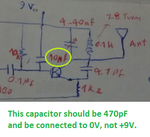
I came up with the following circuit and I faced some problems that I cant solve.
first of all I replaced mic with mono aux cable then I figured it out that voltage is almost 9 volts dc and 18 volts ac at the aux (so this will burn any smartphone right?)
second I couldnt find my transmiter on fm reciver, I found a strong station which is just buzzing and no other sound ...(power source was from pc 12vdc(maybe noicey but I regulated it using 78l09 ic))
third mics doesnt have polarity right?
fourth i couldnt find any trimmer cap so I used 2 diffrent capacitors with a switch(in theory I should have 2 stations)ok?
p.s. package is too small and I used aluminium as shield in the back.
antenna is the green wire inside the package(2inches or more)
if u see anything odd or stupid just tell me
circuit and
my design: tmp-cam-1503702712.jpgtmp-cam--818046901.jpgtmp-cam-646794574.jpg
 
Last edited:

Let us see one at a time:

first of all I replaced mic with mono aux cable then I figured it out that voltage is almost 9 volts dc and 18 volts ac at the aux (so this will burn any smartphone right?)

Do you mean you replaced the mike on the transmitter circuit (seen in Fig 1) with an aux cable? But your smartphone does not have aux out- just use the headphone cable (of the smartphone) - do not use a cable with microphone (with headphones).

If you look carefully at the phone jack, you will know. It should have two rings and one central pin.

Your phone may have phantom power for the mike- we do not need that for this purpose.

About the "other" problem:

your circuit may have too much drift and you may tune it to some frequency but there is no guarantee that it will stay there.

Using a small FM radio, tune your transmitter so that it broadcasts somewhere in the middle of the FM band.
 

    V

    Points: 2
    Helpful Answer Positive Rating
Let us see one at a time:


Do you mean you replaced the mike on the transmitter circuit (seen in Fig 1) with an aux cable? But your smartphone does not have aux out- just use the headphone cable (of the smartphone) - do not use a cable with microphone (with headphones).

If you look carefully at the phone jack, you will know. It should have two rings and one central pin.

Your phone may have phantom power for the mike- we do not need that for this purpose.

About the "other" problem:

your circuit may have too much drift and you may tune it to some frequency but there is no guarantee that it will stay there.

Using a small FM radio, tune your transmitter so that it broadcasts somewhere in the middle of the FM band.

my phone does have a jack 3.5 output, lets clear it out by an example, when I wanna play my music on a speaker I simply connect my phone to aux cable of amplifier powered speaker so at this point I measured voltage of speaker's aux but there no dc or ac voltage, which in my case (aux cable of fm transmitter) is 10vdc and 18vac.,this is abnormal and defenitly will harm any device...
 

I think you are referring to the voltage across the INPUT of your transmitter. It is there only because it is designed to amplify the output of an electret microphone which requires powering. If you remove the microphone and the 10K resistor connecting it to 9V the problem goes away.

However, you may find the phone does not recognize the jack plug is inserted. It depends on the type of phone, some use a mechanical switch which is physically operated by the plug being inserted, some use the current being drawn by earphones to detect it's presence. If yours is the latter type, wire a 470 Ohm resistor across the jack plug, effectively where the electret microphone is now but still leave the 10K resistor out of circuit.

Brian.
 

    V

    Points: 2
    Helpful Answer Positive Rating
Your mike gets 9V DC from the power supply via a 10K resistor. This is needed for the condenser mike (most common) and the AC is coupled via a capacitor to the input.

You may please remove the 10K resistor (connected to the mike) and directly couple the aux input to the capacitor. The DC will be gone and the AC is coming from the oscillator (that will also be gone).

That may be all that is needed. By the osc stability and drift will still be there ...

thanks!!
so is this the improved circuit:
tmp-cam--1730566633.jpg
and any other advice on my circuit!? is the lenth of antenna fine? is it fine to bend antenna to make it fit into the case?
 

Almost right - you should remove the microphone as well and if necessary, add a 470 Ohm resistor in it's place.
The audio then connects across the resistor with the shield in the cable going to the ground side and the inner wire going to the junction of the new resistor and the 0.1uF capacitor.

An antenna works by radiating an electromagnetic field from end to end. If you fold it, the fields will also be folded and inevitably some of the radiation will cancel itself out. It will still work to some degree but nowhere near as efficiently as when straight. Ideally it should be 0.5 wavelengths long (about 1.5m for 100MHz).

Brian.
 

    V

    Points: 2
    Helpful Answer Positive Rating
The transmitter circuit is way too simple and will have very poor performance:
1) The first transistor on the left side of the schematic amplifies the very low level from a microphone. The level from your phone is about 150 times too high and will cause severe distortion on an FM radio. Remove that first transistor and its parts.
2) The antenna is connected directly to the oscillator so the radio frequency will change when something moves towards or away from the antenna.
3) The circuit is missing pre-emphasis that all FM radio stations have and that all FM radios have corresponding de-emphasis so its sounds will sound muffled on an FM radio like your stereo with its treble tone control turns all the way down.


I cannot read your scribbles. If the value of the capacitor on the RF oscillator transistor base to +9V is 10uF then all audio is shorted and the transmitter transmits no audio.
 

Attachments

  • FM oscillator.png
    FM oscillator.png
    96.3 KB · Views: 149
It should also have at least one capacitor (10nF to 100nF) directly across the 9V and 0V points! Mount them at the board, not across the battery because the wire lengths are critical.

Brian.
 

It should also have at least one capacitor (10nF to 100nF) directly across the 9V and 0V points! Mount them at the board, not across the battery because the wire lengths are critical.

Brian.

The 9V regulator also needs this capacitor and an input capacitor that are shown as missing on the circuit board. The regulator's datasheet has a note about it.
 

Status
Not open for further replies.

Part and Inventory Search

Welcome to EDABoard.com

Sponsor

Back
Top