Continue to Site

Welcome to EDAboard.com

Welcome to our site! EDAboard.com is an international Electronics Discussion Forum focused on EDA software, circuits, schematics, books, theory, papers, asic, pld, 8051, DSP, Network, RF, Analog Design, PCB, Service Manuals... and a whole lot more! To participate you need to register. Registration is free. Click here to register now.

Amplifier output mosfet protection

Status
Not open for further replies.

northumber82

Member level 3
Joined
Jan 6, 2018
Messages
66
Helped
2
Reputation
4
Reaction score
2
Trophy points
8
Activity points
564
Hi guys, I designed this amplifier output protection for speakers. This circuit blocks DC output from amplifier and is also an antibump.
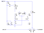
Immagine.png

Originally, the circuit was using a relay, I replaced it with a mosfet relay. There is a problem in that? In simulation I see no problems, but some guys says that there are additional distortion using mosfets at the output.
 

Did you simulate the transient behaviour? Measure the THD on the load with small and high amplitude signals for different frequencies with load. It will tell you the answer.
I think it will cause distortion, I don't know how much, probably high. I think the Ron of 2 series device will vary a lot and comparable with a speaker's impedance.
 

Hi,

The gate is driven HIGH by Q29. But if Q29 is OFF the gate is floating. M3 state undefined.

Maybe there are some other problems:
* case1: AMP_OUT = AMP_V++ (or close to it), then M3:gate is not driven HIGH --> M3 state undefined.
* case2: AMP_OUT = AMP_V-- (or close to it) then V_GS may be overdiven. (sadly we see no voltages)

Does it really simulate with correct function? I´m curious to see your simulation results.

Klaus
 

Did you simulate the transient behaviour? Measure the THD on the load with small and high amplitude signals for different frequencies with load. It will tell you the answer.
I think it will cause distortion, I don't know how much, probably high. I think the Ron of 2 series device will vary a lot and comparable with a speaker's impedance.

Screenshot (40).png

These are simulation results before and after the mosfet driver, seems the distortion is doubled, but ever low. This because the signal is attenuated by RDSon but second and third harmonic are the same.

Hi,

The gate is driven HIGH by Q29. But if Q29 is OFF the gate is floating. M3 state undefined.

Maybe there are some other problems:
* case1: AMP_OUT = AMP_V++ (or close to it), then M3:gate is not driven HIGH --> M3 state undefined.
* case2: AMP_OUT = AMP_V-- (or close to it) then V_GS may be overdiven. (sadly we see no voltages)

Does it really simulate with correct function? I´m curious to see your simulation results.

Klaus

Screenshot (41).png

Simulated in LTSpice using transient analysis, it gives me only an attenuation as I said upper.

In the simulation the protection works perfectly: when insert a DC voltage at amplifier input it interrupt Q29 and mosfets are not driven anymore, anything after the mosfets does not receive any current and voltage.

At low input voltage, the attenuation by mosfets is more consistent, at high voltage there is normal clipping.

What exactly I have to simulate? What to measure?
 

As I mentioned, check THD for different voltage levels (10mV 100mV 1V 10V for example). Not just large signal is important, and check at 20Hz and 20kHz too. And with load! You didn't tell how much was the load which you used for simulation.
By the way the first result looks good, however I don't see why you have distortion before the switch. Probably not important.
And a side question, how much is the maximum DC voltage which can appear on the speaker? Very important.
 
Last edited:

As I mentioned, check THD for different voltage levels (10mV 100mV 1V 10V for example). Not just large signal is important, and check at 20Hz and 20kHz too. And with load! You didn't tell how much was the load which you used for simulation.
By the way the first result looks good, however I don't see why you have distortion before the switch. Probably not important.

Ok then:

At large signal distortion is ever low, but at small signal the distortion difference is very high 0.000018% vs 0.08%.

The load is EVER a 8ohm resistor.

I checked only at 1kHz sine wave.

Probably, MOSfet aren't the best choice for this application. There is a better solution than a relay or mos?
 

0.08% is still ok, you can connect parallel MOSFETs to decrease it more, but check your circuit for different frequencies. And I had a side question, sorry, I updated my previous question, please check that.
I think relay can be the best now (maybe reed-ralays if you don't like the flip-flop sound). If I got something better I will inform you.

Distortion at 20kHz:

Low signal: 0.0005% VS 0.16%
Large signal: 0.007% VS 0.007% (no differences)

"And a side question, how much is the maximum DC voltage which can appear on the speaker? Very important."

Also 0.01V is sufficient to activate the protection.

- - - Updated - - -

I have a question for that, regards damping factor. RDSon of mosfets now works only as attenuation resistor, or increase also the output impedance?
 

Problem of floating gate has been already mentioned and must be fixed, also the circuit should be expected to operate the electronic relays with AC swing over the full AMP_V++ to AMP_V-- voltage swing which is rarely possible with the simple circuit. In addition, the maximal low frequency signal that doesn't trip the protection must be specified. Gate-Source voltage must be clamped to safe levels.

As expected, relative high Rds,on of IRF530 causes some unwanted distortion, you would need a MOSFET pair with lower Rds,on. Also an "over-the-head" gate power supply is required for full undistorted voltage swing. Alternatively, a photovoltaic opto coupler like Vishay VOM1271 can be used. But realistically, a mechanical relays is the cheaper alternative.

RDSon of mosfets now works only as attenuation resistor, or increase also the output impedance?
Surely increase impedance.
 

0.16% is not the best HiFi, but pretty good. What do you mean under low signal? 10mV?
What about 20Hz?
And how any of the Q27 or Q28 will react if you decrease/increase the output voltage with 10mV? I don't see it how the MOSFETs turn-off at such a low output voltage. What do you mean under "Also 0.01V is sufficient to activate the protection."? Could you show a DC sweep maybe at the amplifier's output?
And DC resistance of a 8Ohm speaker is less, like 5-6Ohm. Simulate with a more realistic speaker model.

20Hz:

Large signal: 0.000015% VS 0.000339%
Small signal: 0.000001% VS 0.05%

Large signal: 1V input
Small signal 0.1V input

I test the protection circuit directly with a voltage source and with an amplifier. Due to x20 gain of the amp, I use directly the DC voltage source to test it. For 0.01V I mean inserting a DC voltage directly in the AMP_OUT node, AC passes with no problems.
 

Ok found the source of distortion: lowing the load crossover distortion seem to be higher. MOSFETs act like a unbiased class B amp. Then mosfet are not the best solution
 

Status
Not open for further replies.

Similar threads

Part and Inventory Search

Welcome to EDABoard.com

Sponsor

Back
Top