Continue to Site
Follow along with the video below to see how to install our site as a web app on your home screen.
Note: This feature may not be available in some browsers.
Does it measure reflected wave ? What is the basic principle?
I need a RF bridge design is there any suitable design available?
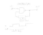
Creating the pulse isn't that difficult, but you need a really fast scope to measure the reflected signal. Really really fast.
OR a slow scope, and use Equivalent Time Sampling. Cheepo $20 impulse radars use this method.