Continue to Site

Welcome to EDAboard.com

Welcome to our site! EDAboard.com is an international Electronics Discussion Forum focused on EDA software, circuits, schematics, books, theory, papers, asic, pld, 8051, DSP, Network, RF, Analog Design, PCB, Service Manuals... and a whole lot more! To participate you need to register. Registration is free. Click here to register now.

Current limiter - Inrush current

Status
Not open for further replies.

Winsu

Full Member level 3
Joined
Oct 25, 2017
Messages
174
Helped
2
Reputation
4
Reaction score
4
Trophy points
18
Activity points
1,691
Current limiter.jpg

Hi All,

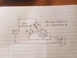
I have posted a very simple circuit to prevent inrush current. It does the job up to 27V and I don't know why at 27V Q1 blows up. I have set the sense resistor to limit the current at 1.8A ( as it is what I would want) and it blows at 27V, and I have changed the current limit and it keeps blowing up. I don't know if I should modified the value of the resistance at the gate of Q1 to improve the performance, but I don't know how that would improve it. I put a capacitor between collector and emitter and it resisted above 30V, but it wasn't limiting the current as it was expected( I guess I modified the voltage dropping at R sense when the capacitor was discharging). What I could do???, any ideas?. I'm thinking to substitute Q2 by an op amp, but I guess the circuit I have posted could do the job with a little change.

The BJT used is 2STD1665T4.

Cheers,
 

What is your load? Inductor or resistor? How much is the value of it? How much is the peak voltage drop on Q1, Vce?
 

The load is 37 ohms in parallel with 1760uf.It is a lamp with some LED drivers.I thinks Q1 collapase before the Led driver start pulling current....It collapse during the charge of the capacitors....I can't rise the limit anymore to reduce the charge period of the caps..The peak of Vce is Vin, whatever it is.

Thanks!
 

Hi,

Worst case the voltage drop across the bjt is 27V and the current is 1.8A.
This means a power dissipation of about 48W.
Multiply it with the r_th_ja of 8.33K/W (given in the datasheet) and get a temperature rise of about 400°C.
This obviously is too hot for the bjt.

BTW: I don't think 8.33K/W is correct. I expect it to be much higher.
Maybe the decimal point is one digit off. I assume 83.3K/W is more realistic than 8.33K/W.
See ST's application note AN1703. Even with a big area of PCB heatsink r_th_ja doesn't drop much below 35K/W.

This makes temperature rise even worse.

Klaus
 

Hi,

I forgot to say that I used a freezer spray to cool down the BJT in case it was a thermal issue. It resisted up to 30V . I have just though that I could used two BJT to split the current. Would it make the circuit more resistant?. Do you think it would resist up to 32V?.

I'm trying to find the datasheet of AN 1703 but I can't find it, is it AN 1703?

Thanks for your help
 

Hi,

I'm trying to find the datasheet of AN 1703 but I can't find it, is it AN 1703?

It´s no datasheet. As said it´s an application note.
Follow the text in red:
findFile.PNG


Klaus
 

You need a power device on a large heatsink to dissipate 48 watts ....

the 2nd breakdown of BJT's makes then a poor choice for this type of application ....
 

Thanks Klaus.

What is your opinion about using two BJT to split the current from the supply to the load. Would it help?
 

Hi,

my recommendations:
1) add a 100 Ohms series resistor to the base of Q2. This prevents the bjt to be killed by overshots on on V_BE
2) don´t use wirewound resistors. They have a lot of series inductance which may cause overshots and oscillation
3) use one (ar as many as you like) suitable power BJT. You need to expect a lot of dissipated (heat) power: P = U x I = 30V x 1.8A = 54W. Your transistor is rated for 15W (absolute maximum!!) only.
4) use a suitable heatsink

Klaus
 
  • Like
Reactions: Winsu

    Winsu

    Points: 2
    Helpful Answer Positive Rating
Hi,

I have tried two used to two BJT and I have changed the limit current 0.85A. Each BJT should dissipate 32V x 0.425A = 13.6W. It is within the BJT spec, and It has killed as well. I don't understand why splitting the current doesn't help.

I'm thinking to order another BJT like the BU406 which is 60w. Would you recommend this one too?.

Cheers
 

I think you cannot connect BJTs in parallel. They have exponential characteristic, small mismatch between devices will cause big difference in their current. So 2 same devices won't share the current equally.
 

Hi,

did you read mypost#2 about r_th?
you need to consider the temperature rise.

Now BU406 case is much bigger than the one before.
But r_th_ja is 60K/W (which makes much more sense than 8.33K/W)
Multiply yor 13.6W with 60K/W and get a temperature rise of 816°C.
Do you think it can withstand it?
--> surely not. You need a big heatsink.

I'm thinking to order another BJT like the BU406 which is 60W.
Read carefully. The test condition is that the case of the BJT is kept at 25°C. Not higher.
Can you ensure this?
--> I don`t hink so.
This is a test condition for the laboratory, just to get meaningful and reproducable specifications.

You have to consider your own "in the field" conditions: ambient temperature range, air flow, heatsink, other heat sources nearby ....

Klaus
 

I also think that Easy's comment about a bipolar transistor's SOA, specifically the secondary breakdown, may be the culprit here.

Can you post the datasheet?
 

Klausst the idea is to get a BJT that can stand at a higher power and with a low r_th_ja?.

I have put a resistor between Emitter of Q1 and base of Q2 and it is performing better, but it gets quite hot. I think the fact that there was no resistor at all was creating the situation that all the current was going though Q4. Does it make any sense??.

Cheers.

- - - Updated - - -

Schmitt trigger, by adding the resistor I'm basically increasing the possibilities of Q2 to survive?. What do you think?

Cheers.
 

Hi,

Klausst the idea is to get a BJT that can stand at a higher power and with a low r_th_ja?.
Please undrstand that r_th_ja depends on heat spreading and not on silicon.
A bigger BJT package helps, multiple BJTs help, but you need a big heatsink anyways.

I have put a resistor between Emitter of Q1 and base of Q2 and it is performing better, but it gets quite hot. I think the fact that there was no resistor at all was creating the situation that all the current was going though Q4. Does it make any sense??.
You can´t prevent the circuit from generating heat. That´s physics.
If it´s now performing better, then it´s more likely that overshot/ringing/oscillating causes the problem.

Do you have low inductive resistors? ...and for sure low inductive wiring?

Do you have a scope to see waveforms caused by fast (swtiching) load impedance?

Klaus
 

This is not really an "inrush current limiter" - it's a poor-boy
current regulator. An inrush current limiter would properly
end up at a "closed switch" (min on resistance, nil voltage
drop) characteristic and this dissipate no continuous power
of any significance. It would only choke current during
supply ramp and maybe short circuit fault conditions.

You might like to go look for "load switch" IC products
with inrush current limiting as a feature, or move to a
PMOS pass device and a smarter gate control.
 

Hi All,

The intention of the circuit was control the inrush current when power up a unit. As the load has a few capacitor the limit had to be quite high to reduce the charge time and burn the BJTs( the BJTs were getting burnt anyway with a quick charge).


Yes Klaus I have an oscilloscope to track the signal, I think I will have to choose a different BJTs, as they are not suitable for this application.

Thanks for your help.
 

Status
Not open for further replies.

Similar threads

Part and Inventory Search

Welcome to EDABoard.com

Sponsor

Back
Top