Continue to Site

Welcome to EDAboard.com

Welcome to our site! EDAboard.com is an international Electronics Discussion Forum focused on EDA software, circuits, schematics, books, theory, papers, asic, pld, 8051, DSP, Network, RF, Analog Design, PCB, Service Manuals... and a whole lot more! To participate you need to register. Registration is free. Click here to register now.

LVD and HVD Protection using PIC12F675

Status
Not open for further replies.

mcmsat13

Member level 5
Joined
Apr 24, 2013
Messages
94
Helped
4
Reputation
8
Reaction score
4
Trophy points
1,288
Activity points
2,287
Hi everyone!

This code is written in CCS C Compiler. The hardware device is 12F675.

I used AN0 and AN1 as the analog voltage sensor inputs.
When the value at AN0 is 1.00V (Normal acceptable voltage level), GP2 becomes High and the transistor drives the LED on. Once High, it should remain High unless the voltage at AN0 is decreased to 0.90V (LVD), and GP2 becomes Low. Once in this state, it will remain Low until the voltage level is >= 1.00 then it becomes High again (LVD Auto Recovery)

HVD part works the same way.
If the voltage at AN1 reads 1.20V (HVD) , GP4 becomes high and Q2 turns the Q1 off. Once HVD is detected at 1.20V, the condition remains until the voltage at AN1 is decreased to 1.10V (HVD Recovery set point), the GP4 becomes Low, the Q2 turns off and D1 is again on.

See the circuit and source code below:

Moderator action: link removed

Now, my problem is this: as the above circuit utilizes two analog pins, AN0 and AN1 and then two digital pins GP2 and GP4, I wanted to use only AN0 as input and only GP4 as the output to perform the same functions but everything I do does not work. I am very new to the MCU code writing, hence I think other people can help me. I am just learning with practice.

Please can someone here help me modify this one below to offer the same functions as the one in the link I posted above?

The LED comes on at 1.00V and should remain on unless the voltage is increased to 1.20V (HVD) then it will off.

When off at 1.20V which is HVD, it will stay off until the voltage is decreased to 1.10V (HVD auto recovery)

The led will also off at 0.90V (LVD) and stays off unless the voltage level comes up to 1.00V (LVD auto recovery)

I wonder if these two functions could be incorporated into one pin like this?

Moderator action: link removed

Any help is appreciated.

I can also accept C codes written MikroC Pro

Thanks all.
 
Last edited by a moderator:
Zip and post the complete mikroC PRO PIC project files and circuit. If you have Proteus circuit then zip it also while posting. I can't download from google drive.

Use Manage Attachment(s) button to attach file.

If you are going to drive just an Led then transistor is not needed. PIC can drive the Led. You can connect RGB Led to show Green for normal V, red for high V and blue for low V.

What do you mean by replace two Analog inputs by 1 ? How will you connect two analog circuits with different voltages to 1 Anx pin ?
 
Last edited:

Hi,

The circuit is not clear. A schematic could clarify this.
Maybe the use of an ADC is a possible solution.

Klaus
 

I am sorry to use external server for my files. Such will not be repeated again...I am sorry.


The working circuit is this:

**broken link removed**

View attachment 12F675 V-Protect 2in-2out.rar

The CCS C code is:

Code:
#include <12F675.h>
#device adc=10
#use delay(clock=4000000)
#fuses NOWDT,INTRC_IO,PUT,NOPROTECT,BROWNOUT,NOMCLR,NOCPD

#define LED1 PIN_A2
#define LED2 PIN_A4

long ad;
float ANALOG;
 
void GetADC(int channel)
 {
   set_adc_channel(channel);             // Set A/D channel
   delay_us(20);                         // Delay acquisition time
   ad = read_adc();                      // Read A/D channel into ad variable
   ANALOG = (float)ad * (5.00/1024);      // Convert 10-bit reading
 }


void init()                               // Hardware initialization
 { 
   setup_adc(ADC_CLOCK_DIV_8);            // A/D clock/8 @4MHz,Tad=2uS
   setup_adc_ports(sAN0 | sAN1);
 }


 void main()
 {
   init();                                 // Configure peripherals/hardware
   while(1)                                // Continuous loop
   {
     GetADC(0);
     if (ANALOG <= 0.90)
       {
         output_bit(LED1,0);
       } 
     if (ANALOG >= 1.00)
             output_bit(LED1,1);

     GetADC(1);
     if (ANALOG <= 1.10)
       {
         output_bit(LED2,0);
       } 
     if (ANALOG >= 1.20)
             output_bit(LED2,1);
     
       }
 }


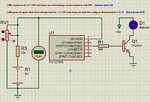
The one I am having problem with is this:

1 In  - 1 Out.jpg
View attachment 12F675 V-Protect 1in-1out.rar

CCS C Code I tried but not working fine is:

Code:
#include <12F675.h>
#device adc=10
#use delay(clock=4000000)
#fuses NOWDT,INTRC_IO,PUT,NOPROTECT,BROWNOUT,NOMCLR,NOCPD

#define LED PIN_A2


long ad;
float ANALOG;
 
void GetADC(int channel)
 {
   set_adc_channel(channel);             // Set A/D channel
   delay_us(20);                         // Delay acquisition time
   ad = read_adc();                      // Read A/D channel into ad variable
   ANALOG = (float)ad * (5.00/1024);      // Convert 10-bit reading
 }


void init()                               // Hardware initialization
 { 
   setup_adc(ADC_CLOCK_DIV_8);            // A/D clock/8 @4MHz,Tad=2uS
   setup_adc_ports(sAN0);
 }


 void main()
 {
   init();                                 // Configure peripherals/hardware
   while(1)                                // Continuous loop
   {
     GetADC(0);
     
     if (ANALOG <= 0.90)
       {
         output_bit(LED,0);
       } 
     else if (ANALOG >= 1.20)
     {
        output_bit (LED,0);
     } 
     else if (ANALOG >= 1.00)
  
     {
     output_bit(LED,1);
     }
    
       }
 }

I want the last circuit to work like:

The LED comes on at 1.00V and should remain on unless the voltage is increased to 1.20V (HVD) then it will off.

When off at 1.20V which is HVD, it will stay off until the voltage is decreased to 1.10V (HVD auto recovery)

The led will also off at 0.90V (LVD) and stays off unless the voltage level comes up to 1.00V (LVD auto recovery)
 

You have to use a variable for hysteresis.
 

Hi,

and I´d avoid to do float calculations during runtime.

To avoid this you could define your thresohld levels as uint16.
pseudo-code:
Code:
constant level09 = 1024 x 0.9 / 5 ; this defines the integer ADC value for 0.9V during compile time
constant level10 = 1024 x 1.0 / 5
constant level11 = 1024 x 1.1 / 5
constant level12 = 1024 x 1.2 / 5
.... 
ad = read_adc();                      // Read A/D channel into ad variable
if (ad <= level09);                    // integer compare example
....

Klaus
 

Mmmm... I finally got it going! I got myself into it and I got myself out of it!

As a beginner, it was weird but I figured some things out and it worked.

I used SUBTRACTION operator to tackle it.

See the new code:
Code:
 {
   init();                                 // Configure peripherals/hardware
   while(1)                                // Continuous loop
   {
     GetADC(0);
     
     if (ANALOG <= 1.32)
       {
         output_bit(LED,0);
       } 
     if (ANALOG >= 1.49 && ANALOG <= (1.99)-0.19) [COLOR="#0000FF"]// The result of the subtraction is the HVD Recovery Set Point [/COLOR]
  
     {
     output_bit(LED,1);
     }

     else if (ANALOG >= 1.99)
     {
        output_bit (LED,0);
     } 
   }
 }

Now I am just playing with the hardware and everything is working fine.

On 24 volt system, it works this way:

* At 21V Sample, the LED is off (LVD)
* When Increased to 24V LED comes on (LVD Auto Recovery)
* If it is increased further to 31V, LED goes off (HVD)
* Coming down from 31V to 29V, the LED comes on again (HVD Auto Recovery)

* Then if the system voltage is >= 29V at initial start up, the LED will not come on. So at start up the system voltage must be below 29V!
 

Status
Not open for further replies.

Similar threads

Part and Inventory Search

Welcome to EDABoard.com

Sponsor

Back
Top