Continue to Site

Welcome to EDAboard.com

Welcome to our site! EDAboard.com is an international Electronics Discussion Forum focused on EDA software, circuits, schematics, books, theory, papers, asic, pld, 8051, DSP, Network, RF, Analog Design, PCB, Service Manuals... and a whole lot more! To participate you need to register. Registration is free. Click here to register now.

[SOLVED] MOSFET gate protection alternative to Zener diode

Status
Not open for further replies.

d123

Advanced Member level 5
Joined
Jun 7, 2015
Messages
2,505
Helped
494
Reputation
992
Reaction score
525
Trophy points
1,393
Location
Spain
Activity points
27,148
Hi,

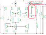
Working on a theoretical circuit and I was wondering if there are any viable and reliable alternatives to using a Zener diode to protect the MOSFET gate from over voltages.

It crossed my mind that an op amp clamp may be feasible but perhaps not up to the job/powerful enough.

No problems with PCB size or suchlike, willing to give anything discrete-based and suitable a go, just seeking input about alternatives to Zener diodes.

Any suggestions?

Example schematic to show what is being referred to:
discrete regulator schematic.PNG

Thanks.
 

What is is about the Zener that you want alternatives, for?
Probably not going to find anything cheaper or smaller.
Though inverse-operated NPN could be an option if you
just happen to like 7V for breakdown. Forward diode stack
varies too much w/ temp, for me to like. Transzorb / active
clamp chips like for pin ESD / EOS protection are zener-like
and maybe worth considering.
 
  • Like
Reactions: d123

    d123

    Points: 2
    Helpful Answer Positive Rating
Hi,

Thanks. Zeners are wasteful, current-wise, and noisy and I just have a relatively objective distaste for them. Diodes are, as you say, temperature performance ruiners, I think, from the simulations I do. Tranzorb is Transil is TVS, isn't it? That will be an option to look into. I initially like the suggestion of the inverse-operated NPN, I'll look into that, shame this PMOS max. VGS is +-10V otherwise maybe stacking two might have been okay.

I'd read that MOVs are an option but I'm not too convinced about that for permanent/long-duration over-voltage events.

I tried the op amp positive clamp and it doesn't seem to fit/be functionally useful either at the regulator input or between the EA output and the MOSFET gate (no wonder, with the latter I guess there's a conflict between regulation feedback and the clamp stuck in the middle). Shame, it would be ideal if it fitted in.

I also tried this circuit but can't seem to get it to do anything useful, not even on its own, so no doubt have been doing something "wrong":

voltage clamp circuits pdf MOS version.jpg

from this pdf:

View attachment VoltageClampCircuits.pdf

I'm under the impression that a TVS is about as good as it gets to sort of avoid Zeners. That, or limiting V in to 10V max. (cop out solution when all else fails).

Thank you for the suggestions.
 

any equivalent to a zener will likely be just as wasteful.

consider an npn BJT with a B-E resistor, say 1K, then put in a B-C resistor say 9k1

now when the external voltage C-E appears and gets up to ~ 5.55V the xtor will turn on - clamping the collector volts ( temp dependent )

but before this happens the current will be ~ 496uA at 5V applied - wasteful..? - perhaps...

the 5v6 zener will be less at 5V applied.

Zeners only work ( draw current ) near the knee point

it seems unlikely you will find as rugged a replacement as a zener that draws less below its clamp voltage ...

( a comparator that turns on a mosfet that connects a zener to the ckt - with a low Iq ref on the comp ...?)

- - - Updated - - -

In the ckt above did you notice that the 2nd fet is a p channel ...?
 
  • Like
Reactions: d123

    d123

    Points: 2
    Helpful Answer Positive Rating
Consider whether the clamp is supposed to be part of the
every-cycle-goings-on, or a backstop for anomalous events.

A proper driver should not be putting overvoltage on the
gate. In this case the clamp has no every-cycle value
and should waste no power.

In this linear regulator setup the zener might be put
further back in the error amp (like, before the output
buffer) rather than having the error amp output butting
heads with it at high load. There is probably some
higher-leverage point that would do, perhaps with a
slightly different zener voltage.

You will need the clamp to stay out of the way from
min to max line, min and max load or it'll bend the
regulation accuracy (fighting w/ error amp).
 
  • Like
Reactions: d123

    d123

    Points: 2
    Helpful Answer Positive Rating
dont think anything better than a zener......but maybe you can avoid the overvoltages by slowing up the switching speed of the fets in the first place......damping the switching transition..though this does increase the switching losses.
 
  • Like
Reactions: d123

    d123

    Points: 2
    Helpful Answer Positive Rating
Hi,

I don't understand something about the simulation results I get for the circuits below. They show the PMOS pass device (not the one gating the Zeners) when off as having an increasing voltage, I would have thought that PMOS would pass no voltage except for maybe mV, especially as there are blocking diodes. It produces the same results with a single comparator or using two separate ones. The rising voltage can be seen better in the upper results. Why is this happening?

VFP problem lm193 discrete.JPG

VFP problem lm193 two.JPG

(Just in case there are doubts about the transistor in the top schematic, it's the open collector/output belonging to the LM193. There is no difference between the comparators in the two circuits. These are both the LM193, a discrete version and the IC version. The discrete version is a faithful copy and it simulates the same as the IC version. There seems no point in posting some huge schematic of the discrete version of the comparator as I believe it won't add anything to the actual question of why the off PMOS output voltage rises and just make the circuit section in question harder to see.)

Thanks.
 
Last edited:

Hi,

T21 is on. Causing your current ...

Erm... Why do you say that? While I'm sure you're right, the simulations give T21 gate voltage as 104mV or at worst 184mV when Vin is an OTT 35V.

I checked this several times last night before posting the question, and to do my due diligence I've checked this again and again this evening to try to understand what you mean but e.g. at V in 10.4V the PMOS gate is at 10.3V, 1uA and the NMOS gate at 49mV.

I would be quite confident saying that in no way is that NMOS on, it needs at least 0.6V to do anything according to the datasheet (simulation of NMOS on own as follower allegedly needs 1.2V to turn on, close to worst case datasheet specs of 1.5V).

At 10.2V the PMOS is gate is in the 200uV range and the NMOS gate in the 10V range but that is clearly not the problem, the PMOS output supposedly rises with rising input voltage and it should do the opposite.

The above are results from the "DC analysis: Calculate nodal voltages" simulation(s), the graphs from yesterday are "DC transfer characteristic, (V in 0V to 35V)". Either analysis - whichever version of the comparator used - shows the comparator output at ~100mV when it goes low.

Really appreciate the reasoning for the comment, thanks, because it puzzles me and I value your experience. Is there any chance the simulator is interpreting gate breakdown as both devices are limited to -10V and 12V, something I find unlikely?
 

I don't understand your considerations. The Vf comp voltage curve shows the rising T21 gate voltage.
 

look at R1, R2, they bias the gate of T21 to 10/11 th's of Vin, hence T21 is on, T20 is on ...
 
  • Like
Reactions: d123

    d123

    Points: 2
    Helpful Answer Positive Rating
Hi,

look at R1, R2, they bias the gate of T21 to 10/11 th's of Vin, hence T21 is on, T20 is on ...

Okay, thanks, really appreciate your input. Thank you. It's not a good design then (no big surprise with my design "skills"). Shame, I like the idea of path A switching out at x voltage and path B switching in.

I'm not expecting an answer as this is more complicated and perhaps conjecture-based and you're a busy person... Any idea why the simulator shows numbers that wouldn't reflect reality - can they sometimes just "mindlessly" number crunch and lead to erroneous results? I try to be wary before making anything as I hate to/can't afford to waste components on looks good on paper, won't work in reality circuits...

Thank you.
 

:bang: :bang: :bang:

I really can't understand why the same thing is happening using 2 PMOS and 2 comparators that carry out the opposite function depending on whether V in is above or below 10V...

If it can be interpreted from the schematic, the transfer characteristic graph and the DC results together, why is the top PMOS always outputting a voltage but "no" current?

Shouldn't the top PMOS output ~0V when the gate voltage is virtually V in?

i hate this circuit vehemently.JPG

Is there something naïve about this design? Any clues as to an alternate design that works/that won't involve seeing the same results over and over again no matter the combinations of N or P?

- - - Updated - - -

...Yet when I simulate the upper PMOS/comparator section on their/its own, the circuit works as I understood it should, i.e. the PMOS turns off and outputs a trivial voltage in the mV range when its gate voltage is virtually V in. Is this possibly the simulation software having some glitch in the results or is there something about such a design that I'm unaware of?

P on its own schematic etc.JPG
 

leakage, you need a pull down resistor just after the fet... - excepting the 1k resistor should provide that ...

- - - Updated - - -

or, something in the sim is just wrong ( and hidden )...

- - - Updated - - -

Also, Vfb comp Pb, being low will turn the pmos on every time ...

- - - Updated - - -

you need pin 3 higher than pin 2 ...
 
  • Like
Reactions: d123

    d123

    Points: 2
    Helpful Answer Positive Rating
Hi,

leakage, you need a pull down resistor just after the fet... - excepting the 1k resistor should provide that ...

You are right. It's working now. Hooray! Thank you very much. It seems I need to read about this topic. If I may ask, why does that resistor make such a difference, (it's not intuitive for me)?

Thank you.

PMOS when off working properly.JPG
 

Attachments

  • PMOS and 1k turn off at last.jpg
    PMOS and 1k turn off at last.jpg
    42.5 KB · Views: 215

Status
Not open for further replies.

Similar threads

Part and Inventory Search

Welcome to EDABoard.com

Sponsor

Back
Top