T
treez
Guest
Hello,
We recently took our 60W Offine , isolated, PFC’d Flyback LED driver (schematic attached) for Conducted and Radiated EMC scans.
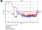
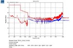
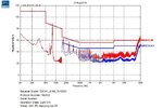
The conducted EMC scan fails at a few spot frequencies as the attached shows.
We also failed Domestic Radiated emissions (CISPR F). –But we passed on Industrial Radiated emissions (CISPR B).
The problem is, that we have no more room on the PCB for any more filter components. As it was, we had to use SMD Y2 capacitors on the bottom of the board because there is no room on the PCB for radial ones.
I believe we need a second common mode choke, but there is no room on the board.
Are there any filter tricks we can pull off here?...unfortunately we aren’t allowed to make the board any bigger.
The ceramic Y2 caps were 3.3nF….but as you know, ceramic X7R capacitors are unfortunately only around 10% of nominal value when operated at rated voltage.
The 60W Flyback’s FET and Diode had small TO220 heatsinks directly connected to them..The FET heatsink is then obviously connected to the drain tab of the FET.…..however, do you agree that this would have made the Radiated scan result worse? (…I believe we should have had an insulating pad between FET heatsink and the FET itself, do you agree?)
During the scans, we had a 60W LED load that we “hacked” together connected……Unfortunately, due to the “hacked nature”, much of the wiring in the LED load bank was not twisted and so there were wide area current loops. The LEDs were on bits of MCPCB, and these were not connected to Earth. The secondary 0V was just “floating”.
(We passed Mains Harmonic Emissions and Power Factor)
VJ2220 SMD X2 and Y2 capacitors
https://www.vishay.com/docs/45020/vjsafetycapsx7r.pdf
ELC09D inductors
www.farnell.com/datasheets/2245397.pdf
Wurth 7448640415 Common Mode Choke
https://katalog.we-online.com/pbs/datasheet/7448640415.pdf
We recently took our 60W Offine , isolated, PFC’d Flyback LED driver (schematic attached) for Conducted and Radiated EMC scans.
The conducted EMC scan fails at a few spot frequencies as the attached shows.
We also failed Domestic Radiated emissions (CISPR F). –But we passed on Industrial Radiated emissions (CISPR B).
The problem is, that we have no more room on the PCB for any more filter components. As it was, we had to use SMD Y2 capacitors on the bottom of the board because there is no room on the PCB for radial ones.
I believe we need a second common mode choke, but there is no room on the board.
Are there any filter tricks we can pull off here?...unfortunately we aren’t allowed to make the board any bigger.
The ceramic Y2 caps were 3.3nF….but as you know, ceramic X7R capacitors are unfortunately only around 10% of nominal value when operated at rated voltage.
The 60W Flyback’s FET and Diode had small TO220 heatsinks directly connected to them..The FET heatsink is then obviously connected to the drain tab of the FET.…..however, do you agree that this would have made the Radiated scan result worse? (…I believe we should have had an insulating pad between FET heatsink and the FET itself, do you agree?)
During the scans, we had a 60W LED load that we “hacked” together connected……Unfortunately, due to the “hacked nature”, much of the wiring in the LED load bank was not twisted and so there were wide area current loops. The LEDs were on bits of MCPCB, and these were not connected to Earth. The secondary 0V was just “floating”.
(We passed Mains Harmonic Emissions and Power Factor)
VJ2220 SMD X2 and Y2 capacitors
https://www.vishay.com/docs/45020/vjsafetycapsx7r.pdf
ELC09D inductors
www.farnell.com/datasheets/2245397.pdf
Wurth 7448640415 Common Mode Choke
https://katalog.we-online.com/pbs/datasheet/7448640415.pdf