shmiv
Newbie level 4
- Joined
- Jul 29, 2010
- Messages
- 6
- Helped
- 0
- Reputation
- 0
- Reaction score
- 0
- Trophy points
- 1,281
- Location
- Durham, NC USA
- Activity points
- 1,345
Hi,
I'm looking to extract the E-field (at various distances) for a thin coil in free space with a specified sinusoidal current in HFSS.
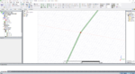
I have a thin 2D coil (10 µm thick) drawn as a sheet and set as a Perfect E boundary. It has a radius of 10 mm. I've created a gap of 10 µm at the left end of the coil, and filled that in with another 2D sheet that's designated as the current excitation at the default of 1 A. The coil is inside a vacuum open radiation boundary.
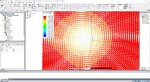
In running the simulation at 450 MHz, everything converges just fine. However, when I look at the E-field 2 mm above the coil, it clearly has the right shape (rotational E-field only), but is not centered on the coil. It almost looks as though the current source is leaking/radiating outside the coil. If I rotate the coil and the location of the current source, this "center" moves with it.
Did I not define the current excitation correctly? Or should I use a different source? The E-field looks right except for where it is centered. Any help is greatly appreciated! I've attached my archived simulation, as well as pictures of the source and vector E-field.
Thanks")
I'm looking to extract the E-field (at various distances) for a thin coil in free space with a specified sinusoidal current in HFSS.
I have a thin 2D coil (10 µm thick) drawn as a sheet and set as a Perfect E boundary. It has a radius of 10 mm. I've created a gap of 10 µm at the left end of the coil, and filled that in with another 2D sheet that's designated as the current excitation at the default of 1 A. The coil is inside a vacuum open radiation boundary.
In running the simulation at 450 MHz, everything converges just fine. However, when I look at the E-field 2 mm above the coil, it clearly has the right shape (rotational E-field only), but is not centered on the coil. It almost looks as though the current source is leaking/radiating outside the coil. If I rotate the coil and the location of the current source, this "center" moves with it.
Did I not define the current excitation correctly? Or should I use a different source? The E-field looks right except for where it is centered. Any help is greatly appreciated! I've attached my archived simulation, as well as pictures of the source and vector E-field.
Thanks