Continue to Site

Welcome to EDAboard.com

Welcome to our site! EDAboard.com is an international Electronics Discussion Forum focused on EDA software, circuits, schematics, books, theory, papers, asic, pld, 8051, DSP, Network, RF, Analog Design, PCB, Service Manuals... and a whole lot more! To participate you need to register. Registration is free. Click here to register now.

Voltage Level Shifting

Status
Not open for further replies.

Rocketman46

Member level 3
Joined
Jan 9, 2014
Messages
57
Helped
0
Reputation
0
Reaction score
0
Trophy points
1,286
Activity points
1,859
Hi all,

I need a bit of advice on what opamp configuration i should use.

I am using a dual supply opamp -5v and +5v and i require the output to swing between 0v to 5v, whilst the input swings between -5v to +5v. I usually work with opamps with inputs between 0v to 5v, but the +/- input has confused me.

Look forward to your reply.

Thanks,

Rocketman46
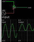
 

Many opamps powered from +5V and -5V have inputs that do not work below about -3.5V or above +3.5V. Also the outputs cannot go higher than about +4V.
Attenuate the signal so it is +2.5V to -2.5V then level-shift it with an opamp with a +6V or higher supply.
 

1) Depending on op amp you may get close, or not, to
the rails for output voltage. Not, if there's any appreciable
load.

2) Signal swing out/in says A=0.5, and you need an offset
term of 2.5V at the output. If you like the qualities of the
-5V supply then this w/ appropriate resistor summing, with
the input signal.
 

Input voltage range is 10V, output voltage range is 5V so your voltage gain is 0.5.
Center of input voltage range is 0V, center of output voltage range is +2.5V so you need a DC offset of +2.5V.
There are many ways to do it, I would suggest an input resistor network to drop the voltage and apply the offset then a unity gain buffer.

Brian.
 

Hi,

Are you talking about
* an analog signal
* or a digital signal --> then use a comparator with push pull output

Klausj
 

Theoretically you can do this by mixing the signal through equal resistors with a 5V supply.

lift signal -5+5V to positive 0 to 5V using single pot.png
 

Hi,

Thank for your replies.

I tried to generate a circuit with the above parameters. Below are my points and circuit. I am struggling a bit as i am a bit weak on analoge.

1) Selected a dual supply rail-rail opamp TI OPA191IDBVT

2) Shifted the input voltage down by 2.5V

3) Calculated the gain on be 0.5

Please feel free to make any comments.

Thanks,

Rocketman46

opamp.png

- - - Updated - - -

Hi,

OK I see I have made a mistake. For gain below 1 an opamp is not required. That is why you mentioned using a resistor network and then a unity gain buffer. My misunderstanding is 0v to -5V voltages. I get +5V to -5V is a 10V swing. I have expanded my design problem below:

1) if 10V is put across two 10k resistors with gnd being 0V, vout out is 5V.

2) when say -2V is put across the two 10k resistors and gnd being -5V, vout will be negative. So therefore vout on the unity gain buffer will be negative? Everything i have done previously is 0V to 5V, i have never really done below 0V designs.

Can anybody help where I am going wrong.

Thanks,

Rocketman46
 

You basic problem is you have no ground (0V). Attenuate the input signal so +/- 5V becomes +/- 2.5V first, then apply it to the op-amp with unity gain but an offset of 2.5V on it's other input -or- on the same input.

Brad's method also works and is simpler but without any buffering at the output it will be influenced by the load. With just an ADC input as load it will probably be fine but be sure the supply lines are present when needed and you don't put a negative voltage on the ADC input. Add a clamp diode across the ADC input if in doubt.

Brian.
 

Hi betwixt,

I am really struggling. Nearly all examples are DC examples for attenuation and cannot I find any negative voltage examples. Excluding the maths and values, I cannot understand how a +- 2.5V turns into a 0V to 5V. 0V and above I semi understand but i do not understand this.

Could you point me to a link that I could work though.

Thanks,

Rocketman46
 

I cannot understand how a +- 2.5V turns into a 0V to 5V
Just add 2.5V.

There are many ways to do it but consider that if you apply a voltage reference to ground to your op-amp, you would expect the output also be reference to ground. For example, assuming unity gain (x1), if you input +0.5V you would expect to get +0.5V out, if you input -0.5V you expect to get -0.5V out. Think about what you are measuring the 0.5V from - it's the 0V (usually ground) that your +5V and -5V supplies are also referenced from.

So if you can lift the input to +2.5V DC above ground, you would expect +2.5V DC at the output. If you reduce your original +/- 5V signal (10V total) so it is only +/-2.5V and add (sum) it at the op-amp input with the +2.5V fixed voltage, you get (2.5V + 2.5V) = 5V and (2.5V - 2.5V) = 0V at the output.

Brian.
 

Hi,

This circuit works on the simulator, my results are below. Is this circuit in the correct direction?. I tried the unity gain buffer option but i could not get to function correctly.

* Vin +5V, Vout +5V

* Vin +2.5V, Vout +5V

* Vin 0V, Vout 2.5V

* Vin -2.5V, Vout 0V

* Vin -5V, Vout 0V


Thanks,

Rocketman46

opamp.png
 

Hi,

The input resistor gain (attenuation) = 1/3
The noninverting Opamp circuit has a gain of 3
Thus the overall gain is 1

But as mentioned above you need an overall gain of 0.5

Klaus
 

I cannot understand how a +- 2.5V turns into a 0V to 5V. 0V and above

Negative voltage means current moves toward it (talking about conventional current).

It is not obvious in my post #6 schematic, that current continually moves from the positive supply backwards toward the incoming signal. This means the source needs to be able to sink current.

On the other hand the output is positive polarity. Current flows from it.
 

Hi,

After lots of testing on the simulator, I can get an output I can use, its not optimum but it works. The only problem I can see is when the input is -5V, the + input on the opamp is in the region of -135mV. To prevent this negative voltage blowing up my opamp and micro ADC port, can i put a BAT54 on the input to prevent the + input swinging negative. As shown in the diagram below?

Thanks,

Rocketman46

opamp2.jpg
 

Status
Not open for further replies.

Similar threads

Part and Inventory Search

Welcome to EDABoard.com

Sponsor

Back
Top