Continue to Site

Welcome to EDAboard.com

Welcome to our site! EDAboard.com is an international Electronics Discussion Forum focused on EDA software, circuits, schematics, books, theory, papers, asic, pld, 8051, DSP, Network, RF, Analog Design, PCB, Service Manuals... and a whole lot more! To participate you need to register. Registration is free. Click here to register now.

Stabilising an ON/OFF controlled SMPS that has low output capacitance.

Status
Not open for further replies.
T

treez

Guest
Hello,
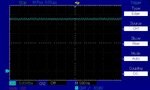
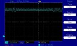
We designed and layed out a 10W, offline, isolated Flyback converter using the TNY287 controller as in the attached schematic. We were not allowed to use any electrolytic capacitors. We only have room for 30uF of ceramic capacitance on the output. The output has a 4V pkpk oscillation on it at some 4kHz…but this is solved when we use the RC network R4 and C3 as in the schematic.
TNY287 is an ON/OFF controller, and the manufacturers recommend high levels of electrolytic capacitance on the output…in our case, the manufacturers software program (PI Expert) recommends 250uF of electrolytic capacitance….but we are just not allowed to use that…and we can only fit 30uF on the board.
Anyway, I was wondering if we could alternatively avoid R4 and C3, and instead achieve “stability” by having a capacitor connected from cathode to anode of the TL431 (U17)?
( I use the term stability with some reserve, because I realise that true “stability” isn’t on the menu for an ON/OFF converter like this.)

Tinyswitch 4 datasheet (TNY287)
https://ac-dc.power.com/sites/default/files/product-docs/tinyswitch-4_family_datasheet.pdf
 

Attachments

  • TNY287 Flyback SMPS.pdf
    48.8 KB · Views: 99

Hi Treez,

What size capacitor will be used? Can you go down a size or two, to fit more on? I think stacking SMD resistors and/or capacitors is sloppy and probably illegal or at least considered a very poor practice, is it, only for modifications to homebrew circuits and prototype work? I read you shouldn't do it... No chance of using TH on the other side of the board and making lead holes?

I don't know if this is any good, it's on the Rod Elliot site amongst many others, at least it'll go in depth a bit. Also, perhaps nor can the 30uF real estate suffice to fit this instead, I suppose.

Transistor Capacitance Multiplier Circuit

**broken link removed**


Transistor Capacitance Multiplier Circuit (different to first one, by the look of it)
 
  • Like
Reactions: treez

    T

    Points: 2
    Helpful Answer Positive Rating
What problem are you trying to solve? The hysteretic control switching too fast or output ripple?

Anyway hysteretic control is hard to screw up, I think it's safe to slow down the control with an integrator.

If I were you I'd also play around with two stage filtering. That should be a good way to reduce ripple with lower C and taking feedback after the second stage may solve that problem as well.
https://ridleyengineering.com/images/phocadownload/1 second stage filter design.pdf
 
  • Like
Reactions: treez and Gouwomb

    Gouwomb

    Points: 2
    Helpful Answer Positive Rating
    T

    Points: 2
    Helpful Answer Positive Rating
What problem are you trying to solve? The hysteretic control switching too fast or output ripple?
We are trying to solve the ripple on vout...we have actually solved it by adding a 47uF , 35V capacitor on vout ...but the boss would rather we didnt have this, due to cost and space. (This capacitor cannot be electrolytic because we are electrolytic-free for reliability purposes)
 

You could increase switching frequency, 4KHz sounds to have a very confortable margin go further.
 

Thanks,thats a good idea...but we are using the TNY287 due to its small solution size...and its fixed at 132khz
 

Ok, so did you try increasing the inductance ?
This would decrease the current ramp on the output capacitor.
 

Thanks, but I have now attached the ripple scopo's as it is without the extra 47uF capacitor being placed on vout….as you can see, this isn’t the switching ripple, this is a feedback loop oscillation.
This problem is totally solved by adding the 47uF capacitor.

It must not be wet electrolytic type, and must not have a limited lifetime…so I will search tantalums and polymer types……
 

Attachments

  • 24v rail at 3W _no 47uF cap on rail.jpg
    24v rail at 3W _no 47uF cap on rail.jpg
    104.8 KB · Views: 121
  • 24v rail at 10W _no 47uF cap on rail.jpg
    24v rail at 10W _no 47uF cap on rail.jpg
    113.2 KB · Views: 128

Thanks,
We need to implement the 47uF , 35V capacitor with a small-as-possible, cheap-as-possible capacitor which has preferably no lifetime issues, or has a long lifetime.
Film capacitors for 47uF , 35V are about 31mm by 18mm by 28mm high…too big and too pricey

So the only capacitor we can go for is as follows……the ZA series Aluminium polymer capacitor…..

ZA series polymer electrolytic capacitor
https://industrial.panasonic.com/cdbs/www-data/pdf/RDD0000/ABA0000C1221.pdf

…these are not “wet” electrolytic, so they will not have anything like the low lifetime issues of “wet” electrolytic capacitors, whose electrolyte just gradually vaporises away.
Are there any new arrivals to the capacitor scene that can do the job better?
 

Hi treez,

I hazard a guess that is a good solution and I would be surprised if you can find a better one. Still no inclination to stack 4 * 10 uF NPO MLCC? ;) Have you seen the size? They're about 6mm x 6mm x 6mm. I almost wanted to suggest this type but needed to check a few details first. I'll guess you're paying between 60p and 1.50 per unit.

The link below may be of interest for the powerpoint document comparing different technologies:

capacitor-selection-types-capacitors

The ppt can't be uploaded here (invalid file) but you can access it by typing SPSCS_7-1b_CapSelect_TypesOfCapacitors into a search engine, or scrolling down in the TI tutorial link to Course documents for download.

It's a nice comparison chart.

Good choice, hope it works well.
 

Status
Not open for further replies.

Similar threads

Part and Inventory Search

Welcome to EDABoard.com

Sponsor

Back
Top