Continue to Site

Welcome to EDAboard.com

Welcome to our site! EDAboard.com is an international Electronics Discussion Forum focused on EDA software, circuits, schematics, books, theory, papers, asic, pld, 8051, DSP, Network, RF, Analog Design, PCB, Service Manuals... and a whole lot more! To participate you need to register. Registration is free. Click here to register now.

please help to automate relay testing

Status
Not open for further replies.

debugtimog

Newbie level 5
Joined
Jul 18, 2018
Messages
9
Helped
0
Reputation
0
Reaction score
0
Trophy points
1
Activity points
121
Hi All,
I would like to ask to help me design a relay tester, that will buzz or light up if the contacts are,say more than 2 ohms. I dont want to use microprocessor, just a simple circuit, maybe a comparator? I want to switch it several times to power up the relay, and I would just know that the relays is faulty each time I press the power button.

Thanks in advance for your help.
 

Hi
you can do it with simple comparator circuit sth like the image I attached photo_2018-08-18_14-02-34.jpg
you can tune the voltage using potentiometer for example on 2 volts (for 2 ohm threshold)
as 1A current source you can use a power supply with current limiter and limit the current on 1A.
this is very simple one with low component number you can better comparator solutions such schmitt trigger , ...
 

Hi,

* specify a measurement contact current
* force this current (I_m) through the contacts. Usually a current limiting resistor should work.
* use a comparator to compare the voltage_across_the_contact with the limit: 2 Ohms x I_m

We don't know about your power supply, your relay voltage and so on, thus it's impossible to give part values.
But using Ohm's law you can calculate them on your own.

Use a paper and a pencil and draw your circuit.

Klaus
 

When contacts are open, is there sufficient voltage available to light an led?
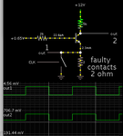
Then the led goes out as soon as contacts close. It is not sensitive enough to a 2 ohm difference, so some kind of amplification is necessary. Possible a transistor operated in common base mode. Low input impedance, high gain, high output impedance.
 

To illustrate common base amplification of signal close to 0V ground.
The relay contacts have the option of good (switch closed), or bad (2 ohm resistance). This mode applies high gain, apparently more than the transistor's beta value. By using a transistor you have readings referenced to a supply rail. However the bias needs to be set precisely, so that you obtain a large difference between good or bad readings. It's a point just about where the transistor starts to turn on.

common base NPN amplifies diff betw good contacts vs 2 ohm.png
 

Status
Not open for further replies.

Similar threads

Part and Inventory Search

Welcome to EDABoard.com

Sponsor

Back
Top