Continue to Site

Welcome to EDAboard.com

Welcome to our site! EDAboard.com is an international Electronics Discussion Forum focused on EDA software, circuits, schematics, books, theory, papers, asic, pld, 8051, DSP, Network, RF, Analog Design, PCB, Service Manuals... and a whole lot more! To participate you need to register. Registration is free. Click here to register now.

[SOLVED] Folded cascode output resistance

Status
Not open for further replies.

khaled2k

Member level 2
Joined
May 14, 2009
Messages
51
Helped
3
Reputation
6
Reaction score
3
Trophy points
1,288
Location
Germany
Activity points
1,635
Hi all,
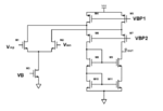
I have a folded cascode opamp with NMOS differential input and the current is steered in PMOS cascode.
The output conductance of all transistors should be theoritically abreviated as
gds= λ Id
I have noticed that for M5 transistor, the simulated gds is much larger than expected.
Let us say for example I5= 50 µA, gds5= 30 µS (Here λ= 0.6V -1)
While for M7, I7= 30 µA, gds7 = 3 µS (Here λ= 0.1V -1)
Even the two transistors are PMOS. Does anyone has an explanation for this?

Thank you guys in advance.
 

Attachments

  • opamp-folded-casc.png
    opamp-folded-casc.png
    16.4 KB · Views: 186

Which process node is this/or which version of model files are you using?
The concept of lambda does not really hold true for submicron process nodes.
 
True, and the 2 transistors have to operate in saturation. If Vds is smaller than Vdsat the drain-source conductance can arise in a non-linear way.
 
gds = Lambda * Id is correct when your transistor is fully in saturation.

I am guessing your M5 is close to linear region that is why your rds drops or gds rises.

Try to bias them properly, it will work.
 
Thank you guys for your answers.
Vivek Roy, you are right. I am workng in submicron.
frankrose, the transistor is at the border of saturation or somehow in triode region so the gds formula should include (Vgs-Vt). In other words gds is higher than calculated by λ Id.
One solution I found useful to scale L while keeping (W/L) constant or maybe adjust the bias like Ata_sa16 suggested.
 

Decrease VBP2, so the Vds of M5 will increase. That is all you need.
 
Thanks frankrose. It is perfect. Now as VBP2 decreases, (VSG-|Vt|) of M7 increases and with the same current, VSD of M7 decreases. This means an increase in VSD of M5 which pushes it more into saturation. Thanks a lot.
.
 

Even if M5 is in saturation, it may present higher gds ( low Ron) since more current is in M5 than other transistors.
 

Status
Not open for further replies.

Part and Inventory Search

Welcome to EDABoard.com

Sponsor

Back
Top