Continue to Site

Welcome to EDAboard.com

Welcome to our site! EDAboard.com is an international Electronics Discussion Forum focused on EDA software, circuits, schematics, books, theory, papers, asic, pld, 8051, DSP, Network, RF, Analog Design, PCB, Service Manuals... and a whole lot more! To participate you need to register. Registration is free. Click here to register now.

[SOLVED] Virtual ground in op amp circuit design

Status
Not open for further replies.

vinctal

Newbie level 4
Joined
Oct 13, 2016
Messages
6
Helped
0
Reputation
0
Reaction score
0
Trophy points
1
Activity points
76
Hi

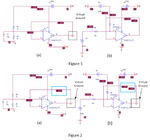
I have simulated 2 circuit in PSPICE, Figure 1(a) and Figure 2(a) is a virtual ground circuit a voltage reference of 5Vdc The two resistors form a voltage divider so that Vcc/2 appears at the non-inverting input of the op amp. Since it is set up as a follower, Vcc/2 also appears at the output.

Can someone explain to in Figure 2(b) why the output voltage is equal to Figure 2(a) ?

Thank you
virtual ground.png
 

Hi,

I assume Fig 2b is wrong.
Ican't find the difference to Fig 1b regarding curcuit, parts and part values. In my eyes they are identical. Thus the voktages should be identical, too.

Btw: the GND symbol at the outputs of the Opamps is confusing.

Klaus
 

Hi,

I assume Fig 2b is wrong.
Ican't find the difference to Fig 1b regarding curcuit, parts and part values. In my eyes they are identical. Thus the voktages should be identical, too.

Btw: the GND symbol at the outputs of the Opamps is confusing.

Klaus

Hi ,

I have update the simulation result. kindly refer to the attached figure.
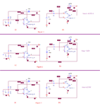
Figure 1(a), Figure 2(a) and Figure 3(a) are the same circuit. ( a virtual ground circuit, where the output voltage of the op amp = Vdc/2)
so output voltage of the op amp in Figure 1(a), Figure 2(a) and Figure 3(a) is 2.50 V.

In Figure 2 and Figure 3, the output of the op amp (a) and (b) are connected. Based on the simulation result in PSPICE, can anyone explain why the output voltage in Figure 2(b) is 2.00 V and Figure 3(b) is 2.50 V ?

Thank you

virtual ground V3.png
 

Your Spice program does not know that we never short together the outputs of opamps. Why do you?
Also, why are your voltage divider resistors such a low value when the input current of the opamps is almost nothing??
 

can anyone explain why the output voltage in Figure 2(b) is 2.00 V and Figure 3(b) is 2.50 V ?
........
As AG noted you are doing something that's not allowed, connecting two op amp outputs together, which will give flaky operation
Correct that error and get back with us on the results.
 

Status
Not open for further replies.

Similar threads

Part and Inventory Search

Welcome to EDABoard.com

Sponsor

Back
Top