Continue to Site

Welcome to EDAboard.com

Welcome to our site! EDAboard.com is an international Electronics Discussion Forum focused on EDA software, circuits, schematics, books, theory, papers, asic, pld, 8051, DSP, Network, RF, Analog Design, PCB, Service Manuals... and a whole lot more! To participate you need to register. Registration is free. Click here to register now.

[SOLVED] squarewave inductive reactance

Status
Not open for further replies.

Zak28

Advanced Member level 2
Joined
Aug 19, 2016
Messages
579
Helped
6
Reputation
12
Reaction score
6
Trophy points
18
Activity points
4,681
Whats the easy way to obtain inductor impedance fed with square wave? It cannot simply be ωFL since afaik thats only applicable for sine waves.
 

There's no thing like "square wave reactance". Reactance is only defined for sinusoidal excitation. The current waveform observed with a square wave voltage across an inductor is a triangle not a square wave. If you calculate the ratio of inductor voltage and current with square wave, you get different results for RMS, peak-to-peak or average rectified value. Need to specify the question clearly.
 
  • Like
Reactions: Zak28

    Zak28

    Points: 2
    Helpful Answer Positive Rating
There's no thing like "square wave reactance". Reactance is only defined for sinusoidal excitation. The current waveform observed with a square wave voltage across an inductor is a triangle not a square wave. If you calculate the ratio of inductor voltage and current with square wave, you get different results for RMS, peak-to-peak or average rectified value. Need to specify the question clearly.

Any AC causes an inductor to make an impedance, even a square wave. My question is extremely clear and obvious, you just misappropriated it.
 
Last edited:

Determine current and voltage waveforms for the problem of interest, explain what you consider as reactance or impedance.

Quite generally impedance Z = V/I, how do you measure V and I?
 
  • Like
Reactions: Zak28

    Zak28

    Points: 2
    Helpful Answer Positive Rating
Determine current and voltage waveforms for the problem of interest, explain what you consider as reactance or impedance.

Quite generally impedance Z = V/I, how do you measure V and I?

Thats incorrect, there are time differences in the values and your making a simple question seem more complicated than it should be.

- - - Updated - - -

Im just going to sim it with LTSPICE, I suppose its going to end up more accurate anyways.
 

Thats incorrect, there are time differences in the values
Whow, now you are bringing in complications. I'm just writing "V" and "I", without further qualification. Consider some kind of average values, e.g. RMS.

I guess you found out in the meantime that the answer is more complex than the oversimplified question?

You need at least to clarify if the excitation is by square wave voltage or current. Ideal (zero rise time) square wave current involves the problem of generating infinite voltage during edges.

A reasonable setup could be square wave voltage and RMS voltage and current values.
 

Any AC causes an inductor to make an impedance, even a square wave. My question is extremely clear and obvious, you just misappropriated it.

Wow, pretty rude response from someone who doesn't know the answer.

Your question is NOT extremely clear or obvious. A square wave has odd harmonics, and, thus, the impedance will be different for each harmonic. What are you really asking?
 

The formula for inductive reactance applies to sines and we can use it as a place to start when we look at results from a square wave:

X = 2 Pi F L

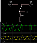
This simulation has only an inductor load. The switch selects either sinewave or square wave. Both supplies are nominal 10 VAC.

The square wave creates an Ampere waveform shaped like a triangle wave (per FvM's' post #2). It is not very different from the sine in shape or amplitude.

inductor input sine comp'd to square wave has triangular current.png

The switch was thrown midway through the run.
 

Whats the easy way to obtain inductor impedance fed with square wave? It cannot simply be ωFL since afaik thats only applicable for sine waves.
I understand from your question that you want to get the transfer function of a pure inductor when it is excited by a square wave. So, we should define the transfer function first: Is it the ratio between the voltage and current (the impedance) in the frequency domain?
If the answer is true, then we cannot access this question using omega domain (or Fourier Transform). We use Laplace transform instead.
I mean that, as long as the excitation is not sinusoidal, we cannot use the formula Z = jwL, as we will not be dealing with omega domain in the circuit. We will not solve such circuit using omega domain. Then, we use Laplace domain and say simply that Z = SL, where S is the complex frequency used in Laplace domain.
If your purpose is to know the waveform of the inductor output due to square wave input, it is rather simpler to use time domain in this case. The inductor voltage and current are simply related by v = L di/dt. If the voltage is square wave, then the current is the integral of the square waveform and so is triangular waveform.
If the current is itself square wave, then the voltage will be a series of shots (impulses) at the instant of current step transitions.
Hope this helps.
 

Status
Not open for further replies.

Similar threads

Part and Inventory Search

Welcome to EDABoard.com

Sponsor

Back
Top