Continue to Site

Welcome to EDAboard.com

Welcome to our site! EDAboard.com is an international Electronics Discussion Forum focused on EDA software, circuits, schematics, books, theory, papers, asic, pld, 8051, DSP, Network, RF, Analog Design, PCB, Service Manuals... and a whole lot more! To participate you need to register. Registration is free. Click here to register now.

SPWM converter mosfet failure

Status
Not open for further replies.
As you turn off your MOSFET there will be a reverse current from the transformer. In H bridge that is normally passed through the free wheeling diodes.

- - - Updated - - -

No need to lower the PWM frequency, you need to make some arrangement to manage the reactive power during turn OFF. Kindly refer the other inverter whether they have dead band shorting MOSFET's also the pwm frequency.

By dead band shorting you mean a dead time between the end and the start of the opposing signal?

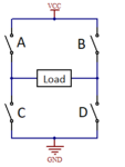
How would this schematic look if I used H bridge? Do I need to change the code or just feed the same signal to the opposite corner MOSFETs? I mean appart from the high side switching driver.
 

By dead band shorting you mean a dead time between the end and the start of the opposing signal?

How would this schematic look if I used H bridge? Do I need to change the code or just feed the same signal to the opposite corner MOSFETs? I mean appart from the high side switching driver.

Ok so i tried something, i made the new PCB and i noticed something. When i had one mosfet in like, half swtching, the transformer was working "fine", it didnt get burned or hot or anything. i tried both windings each every time. I even put a lighbulb and it lighted up. Later i put both transistors and they got burned.
 

The result is rather unspecific, though. Can be a case of wrong switching pattern or leakage inductance generated overvoltage increasing a bit when activating push-pull operation. Need to look at the waveform details.
 

I believe a push-pull with one primary leg open, devolves
to a flyback (primary upside down, but still).

Now one thing I see missing from this push-pull design is
the "flywheel" inductor that keeps the secondary current
circulating (rather than extinction each half cycle).
There is only the transformer, bridge and load.
 

The result is rather unspecific, though. Can be a case of wrong switching pattern or leakage inductance generated overvoltage increasing a bit when activating push-pull operation. Need to look at the waveform details.

hhhhh.PNG
dfsd.PNG

So this is my waveform. This is what i feed in my mosfets(amplified to 12v with my mosfet driver). This is the almost max pwm (meaning more pulses and longer in the period) and as you can see there is more than enough time between the pulses for the mosfets to be on and off. Around 150uS. What can i do about leak inductance if thats the case?

- - - Updated - - -

I believe a push-pull with one primary leg open, devolves
to a flyback (primary upside down, but still).

Now one thing I see missing from this push-pull design is
the "flywheel" inductor that keeps the secondary current
circulating (rather than extinction each half cycle).
There is only the transformer, bridge and load.

What is this flywheel inductor? Where do i put it? And how to calculate it? i couldn't find much in google
 
Last edited:

The gate drive waveform seem to indicate a correct control pattern. I don't understand where the negative gate voltage level comes from.

Regarding leakage respectively flywheel inductance, I doubt that this push-pull topology is suited for SPWM at all. Stored energy is partly recovered through substrate diode of the inactive transistor and partly burned in avalanche breakdown.
 

Quick update. I measured the inductunces of the windings. The secondary is 1.6H and the primaries are 12uH and 12.63uH. does this mean anything?
 

Hi,

I rather expect 12mH than 12uH...
How did you measure it?

Klaus
 

Hi,

Again: how did you measure it?
I mean: the primary side has three connections but the meter usually only two.
And what frequency, what voltage/current, pure sine?

Klaus
 

Hi,

Again: how did you measure it?
I mean: the primary side has three connections but the meter usually only two.
And what frequency, what voltage/current, pure sine?

Klaus

I measured center tap to the other two. Common to ct and then i changed.

My meter is pretty basic, it automaticaly measures. It says F=506khz the voltage is 5V. I cant choose those settings.
 

Hi,

I measured center tap to the other two. Common to ct and then i changed.
The other two shorted? --> This explains the low inductance.

Let's assume you have a transformer with split output...would you ever short them, too?

Useful measurement setup is to measure just a single winding (leaving the other open), or to measure both windings in series (leaving the center tap not connected).

Klaus
 

Hi,


The other two shorted? --> This explains the low inductance.

Let's assume you have a transformer with split output...would you ever short them, too?

Useful measurement setup is to measure just a single winding (leaving the other open), or to measure both windings in series (leaving the center tap not connected).

Klaus


(Crude paint graph warning)

No, i didn't short anything. I left everything open. I measured One time between 1 and 2 and the second time between 2 and 3. The black wire stayed connected i just changed the red one.

reereree.png

When i measured the total inductance 1 - 3 i measured around 50uH
 
Last edited:

If you measure it in situ then you will see that secondary
"shorting" cap reflected back to the primary. That might
mess up an inductance meter's idea of what it's looking at.
 

'in situ' means 'while connected in the circuit'. To do the tests you need to disconnect all the windings then check each one as before.

Brian.
 

'in situ' means 'while connected in the circuit'. To do the tests you need to disconnect all the windings then check each one as before.

Brian.

As I said before I measured it while it wasn't connected or shorted :) still I get 12uH and 12.6uH at the secondaries
 

By feeding the complement signal to the bottom MOSFET (with few micro seconds dead time) . You can easily convert it to h bridge. Make sure that you use split bobbin transformer.
 

By feeding the complement signal to the bottom MOSFET (with few micro seconds dead time) . You can easily convert it to h bridge. Make sure that you use split bobbin transformer.

Hey,

I have 2 signals with spwm and plenty of dead time between them. What i saw about H Bridge is I must feed the one signal to the A and D mosfets and the other to B and C mosfets. Will this work this way assuming i have 100+uS between the signals?

H-bridge_fig1.png

Κυμματομορφη 1.PNG

Why use split bobbin transformer? The ones i have are single bobin ones. Whats the difference of a "normal" one except better isolation?
 
Last edited:

Hey,

I have 2 signals with spwm and plenty of dead time between them. What i saw about H Bridge is I must feed the one signal to the A and D mosfets and the other to B and C mosfets. Will this work this way assuming i have 100+uS between the signals?

View attachment 148326

View attachment 148327

Why use split bobbin transformer? The ones i have are single bobin ones. Whats the difference of a "normal" one except better isolation?

Split bobbin will increase your leakage inductance which is required to filter the HF. You may apply SPWM 1 to A and 2 to B. Complement of 1 should be given to C and 2 toD
The dead time is to be given for the compliment signal.
 

Status
Not open for further replies.

Similar threads

Part and Inventory Search

Welcome to EDABoard.com

Sponsor

Back
Top