Continue to Site

Welcome to EDAboard.com

Welcome to our site! EDAboard.com is an international Electronics Discussion Forum focused on EDA software, circuits, schematics, books, theory, papers, asic, pld, 8051, DSP, Network, RF, Analog Design, PCB, Service Manuals... and a whole lot more! To participate you need to register. Registration is free. Click here to register now.

Complementary switching on ac signals

Status
Not open for further replies.

mheruian

Junior Member level 3
Joined
Jan 18, 2018
Messages
31
Helped
0
Reputation
0
Reaction score
0
Trophy points
6
Activity points
412
Hi i'm just a starting out hobbyist who knows how to use arduino in switching purposes but there is this switching scheme i want to perform but didn't work out the way i thought it was when i simulate it. Though given i have references provided by guys here told me to follow. I'm not much knowledgeable about the different matters about transistors. All i know about them is these are like switches on saturation.
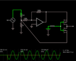
simu-3.PNG

above is the circuit i simulated using this site https://www.falstad.com/circuit/

it's a circuit where i want the hi-ac voltage be turned into small value and will act as a small signal analog for input testing. Originally, it doesn't have those complementary mosfets so basically the outputs will be from the two end points where the difference is their phasing only, one is reverse using the inverting op amp configuration (w/c i learn at youtube tutorial only).

now i want to create a one end output only where it'll either output the non-reversed phase or reversed phase via 1 switching only (either coming from spdt switch, another transistor, ICs like DMX, i/o expanders, microcontroller, etc.) i even wanted to put a pull down diode and resistor setup on the gates of the complementary mosfets to give state indicator. But this setup doesn't work the way i think because every time i open the switch, it doesn't reverse the phasing - it doesn't even have output (0 volts).

in short, i want to create a dpst (double pole single throw) digital switch for my two AC outputs having 180 degree phase difference, i don't want to use ssr or relays. :'( i hope you can help me.

my references are below:
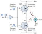
sample.png sample-2.gif
 

Hi,

a FET is switched ON/OFF according it´s voltage between gate and source = V_GS.
In the FET´s datasheet you find the threshold voltage at which the FET starts to become conductive. This is V_GS_th

In the reference circuit below .. the source voltages of the FET are at fixed DC volts (+VDD and -VDD),
But in your example both source voltages are AC. Sometimes they are positive, sometimes they are negative.
And if you want that V_GS of the FET is constant (for piece of time), then the gate voltage (referenced to GND) needs to vary, too.

For the simulation I recommend to use a load resistor at the output to avoid a flaoting signal.

For the real circuit I recommend to replace the FETs with an analog_switch. It should be controlled by a logic signal, maybe generated by a comparator.

For the overall idea:
It seems you want to build an active_precision_rectifier: If so, then there are more simple circuits available.


Klaus

Hi Mr.Klaus,

Thanks for replying, i did include a load resistor on the simulation but it didn't still work.

I tried searching analog switches and i think this is really what i need but is there no really other way to work it out using those p-n channel mosfets like just adding few components etc?

I started looking for analog switches online that i could use but i ended up in some confusion where i did search a lot on the web but never find a strong tutorial or technical information about this switches - terms, rail-to-rail (negative to positive polarities?) and the others that doesn't have that term. I saw V+ and V-, also Vcc and Gnd on others and Vee. Does that mean analog switches that only has Vcc and Gnd cannot pass an analog signal having negative and positive value? (alternating voltage)?

can i not use this for my non-reversed and reversed phased small signal https://www.ti.com/lit/ds/symlink/ts3a44159.pdf

how about also this one https://datasheets.maximintegrated.com/en/ds/MAX4661-MAX4663.pdf? though this one is so expensive, any same cheap IC used from previous experience that has 2 or 4 channels also?

the circuit actually is just a signal that'll use as an input on a analog chip instead of a signal coming from a sensor. A guy here told me sensor values after all are just small voltage signal values so even w/o sensor, as long as i'm on the valid parameter he said, i can have a pseudo constant sensor value for testing purposes only.

EDIT: added the max4661-max4663 IC
 
Last edited:

Hi,

but is there no really other way to work it out using those p-n channel mosfets like just adding few components etc?

As said: there are other circuits.
But to recommend a circuit, we need to know what it should do.
Pleae describe it as a black box, not internal parts, just the signal you want.
Voltages, frequencies, waveforms...all that is important for you.
Outputs and inputs, if there are any.

If there already exists a power supply, then tell us the values.

***********
To your other text:
technical information about this switches - terms, rail-to-rail (negative to positive polarities?) and the others that doesn't have that term. I saw V+ and V-, also Vcc and Gnd on others and Vee. Does that mean analog switches that only has Vcc and Gnd cannot pass an analog signal having negative and positive value? (alternating voltage)?
The very most electronic circuits can only work/generate signals within their supply rails.
This is mostly not defined by keywords, but by technical specifications.

Named : "xxx input voltage range" and "xxx output voltage range".

Klaus
 

Hi,


As said: there are other circuits.
But to recommend a circuit, we need to know what it should do.
Pleae describe it as a black box, not internal parts, just the signal you want.
Voltages, frequencies, waveforms...all that is important for you.
Outputs and inputs, if there are any.

If there already exists a power supply, then tell us the values.

***********
To your other text:

The very most electronic circuits can only work/generate signals within their supply rails.
This is mostly not defined by keywords, but by technical specifications.

Named : "xxx input voltage range" and "xxx output voltage range".

Klaus

Hi,

Ok, i get it. thanks a lot :)
 

Status
Not open for further replies.

Part and Inventory Search

Welcome to EDABoard.com

Sponsor

Back
Top