Continue to Site

Welcome to EDAboard.com

Welcome to our site! EDAboard.com is an international Electronics Discussion Forum focused on EDA software, circuits, schematics, books, theory, papers, asic, pld, 8051, DSP, Network, RF, Analog Design, PCB, Service Manuals... and a whole lot more! To participate you need to register. Registration is free. Click here to register now.

Output Voltage and Charging time of capacitor when discharge resistor is used

Status
Not open for further replies.

dev514

Newbie level 4
Joined
Jul 23, 2018
Messages
6
Helped
0
Reputation
0
Reaction score
0
Trophy points
1
Activity points
51
final.PNG


Hi all,


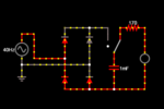
I am struggling with a circuit calculation and quiet confused in analyzing the circuit.In the above shown image the input ac voltage is 4v and is rectified with bridge wave rectifier which is then fed to another circuit which stores and discharges the charge to a LED through a resistor.We use a SPDT switch in here.Which connects the capacitor with the bridge wave rectifier at one position and charges on the other hand when the switch is changed the capacitor is connected to the LED through resistor.My doubt is can i use time constant T=RC to calculate the charging time of capacitor.But how can i use T=RC when there is no resistor connected.The resistor is a capacitor discharge resistor so how do i calculate the charging and discharge time? and how to finally calculate the output voltage? :???:

thank you in advance...

Regards,

San
 

Hi,

I don't think the circuit - especially the SPDT - makes sense.

T = RC is mainly useful for DC charge/discharge voltage, but you don't have DC.

"No resistor connected":
The source, the diodes and the wiring will form a resistance. But it is neither constant, nir linear.
For a dedicated point of time, with known voltages you may calculate it ... but this will not help you here.

I wonder what you want to achieve.....or is it a school project?

Klaus
 

Hi Klaus,

No its not a school project.It's a POC.Also the output is obtained form a bridge wave rectifier.So it has to be a dc?I want to know how to calculate the charging time and discharging time of the capacitor.Also want to know if the output voltage can light a LED constantly when the input voltage is 4v AC?Kindly help or provide some ideas if possible so that i can design it in a better way or predict the output of this circuit.

- - - Updated - - -

The capacitor charges due to the dc output from the bridgewave rectifier at one position of the SPDT switch and discharges through the resistor when the SPDT position is changes.

- - - Updated - - -

Hi,

I don't think the circuit - especially the SPDT - makes sense.

T = RC is mainly useful for DC charge/discharge voltage, but you don't have DC.

"No resistor connected":
The source, the diodes and the wiring will form a resistance. But it is neither constant, nir linear.
For a dedicated point of time, with known voltages you may calculate it ... but this will not help you here.

I wonder what you want to achieve.....or is it a school project?

Klaus

Hi Klaus,

No its not a school Project.Its a POC given to me by my organisation.The output from the AC is given to the bridge wave rectifier so DC will be obtained.It's like the capacitor charges from the output of the bridge wave rectifier at one position of the SPDT switch and discharges through the resistor at other position of the SPDT switch.I am confused in calculating the charging and discharging time of the capacitor also the output voltage if possible to light the LED constantly if the input is 4v.Kindly provide some ideas so that i can design it in a better way or will be able to calculate the output of this circuit
 

Hi,

Also the output is obtained form a bridge wave rectifier.So it has to be a dc?
I recommend to use a simulation tool. Like LTspice, it is free and easy to use.
At least take a sheet of paper and a pencil and draw the input waveform and your switching waveform, then you easily will find out where the problem is.

DC means a straight horizonzontal line on a scope.
A rectified sine is far away from this.

Maybe you think everything that is not going negative is DC ... then do you consider a 1kHz 0V/5V square wave with 50% duty cycle "DC", too?

If you want the bridge output to be considered as "DC" , then you need a fixed (not switching) additional capacitor directly at the bridge output.


I want to know how to calculate the charging time and discharging time of the capacitor
Since your input is not DC, there is continously changing voltage --> continously changing conditions = continously changing time constant.

****
Switching a capacitor without dedicated series impedance may cause high current peaks, causing much EMI problems.


Klaus
 
  • Like
Reactions: dev514

    dev514

    Points: 2
    Helpful Answer Positive Rating
I'm confused (again).
It seems to be a simple bridge rectifier charging the 1mF (1,000uF) capacitor when the switch is to the left. When moved to the right, it discharges the capacitor through the resistor to the LED.

Charging time depends on several factors: the source impedance, the resistance of the rectifiers, the ESR of the capacitor and wiring resistance. For most practical purposes the capacitor will charge almost instantly to (VAC - (2 * rectifier Vf)) volts. In other words it's voltage will follow the AC waveform voltage minus the drop across the diodes. As Klaus points out, with nothing to limit the current it could be significant until full charge is reached. Ignoring series resitances, with 4V RMS input, the capacitor should reach about 4.25V after one half cycle.

Discharge also depends on several factors. The T=CR formula applies but an LED doesn't provide a constant 'R', in fact it goes virtually open circuit as the voltage drops below the LED's Vf. The first thing you have to know is what Vf actually is, some LED's have a Vf higher than 4.25V so it would never light up anyway. The actual load current and hence time the LED lights up is a combination of the fixed 170 Ohm resistance and the non-linear resistance of the LED. For example, if the LED VF is say 1.6V (typical for a small red LED) the capacitor voltage will drop from 4.25V with decreasing rate of discharge until it has about 1.6V across it then the discharge will be significantly slower.

As you can see, it isn't a straight forward calculation and a simulation, which takes into account real life parameters, is a good option for finding out what really happens.

Brian.
 
  • Like
Reactions: dev514

    dev514

    Points: 2
    Helpful Answer Positive Rating
To get a feel, do this graphically.

4V RMS is 4*1.4 peak. Draw the sine wave (negative side folded to top side).

Since the voltage is small, you need to account for the two diode drops. Remember that the diode drops depends on the current.When the switch is to the left, load is virtually a short.

Approx the current (typ value) to the avg capacitor current. Look up the voltage drop from the diode I-V graph.

Assume the source resistance is zero but the diode will have some dynamic resistance. Estimate the diode resistance (two drops) from the graph.

Use that with the capacitor to get the time constant. The capacitor will charge to the max voltage (it will never reach the final value) but a steady state estimate will be easy (calculations for the first cycle will be wrong).

On the other side (capacitor is discharging), the LED is another diode with a large drop and small resistance. Add that to the series resistance.

These are all approximations but graphical analysis is highly illustrative.
 

Status
Not open for further replies.

Part and Inventory Search

Welcome to EDABoard.com

Sponsor

Back
Top