Continue to Site

Welcome to EDAboard.com

Welcome to our site! EDAboard.com is an international Electronics Discussion Forum focused on EDA software, circuits, schematics, books, theory, papers, asic, pld, 8051, DSP, Network, RF, Analog Design, PCB, Service Manuals... and a whole lot more! To participate you need to register. Registration is free. Click here to register now.

Sensing mains input current in offline SMPS

Status
Not open for further replies.
T

treez

Guest
Hello,
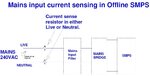
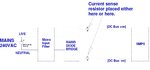
We sometimes monitor the input current to our offline SMPS’s by using a diff probe and scope to observe the voltage across a sense resistor at the input to the SMPS (as in the attached diagram).
Why is it that the reading is always more noisy (and this is seen as ‘more ‘fuzz’ on the scoped waveform) when the sense resistor is placed in the Live line as opposed to the Neutral line?
 

Attachments

  • Offline SMPS current sensing.jpg
    Offline SMPS current sensing.jpg
    114.3 KB · Views: 163

Re: Sesning mains input current in offline SMPS

Hi,

Either common mode noise (not sufficiently suppressed), from mains or from the scope.
Or real noise current through this line.
What does the GND current look like?


Klaus
 
  • Like
Reactions: treez

    T

    Points: 2
    Helpful Answer Positive Rating
Re: Sesning mains input current in offline SMPS

Thanks
If the sense resistor is placed just downstream of the mains rectifier bridge, (as in the attached schamtic) then it shouldn’t matter whether the sense resistor is placed in the [DC Bus –ve] or the [DC Bus +ve]. Either place should be equal from a noise point of view, since each node alternately connects to mains live then mains neutral.
However, even in this case, I always seem to see less noise when the sense resistor is connected into the [DC Bus –ve]. Do you know why?
 

Attachments

  • Offline SMPS current sensing___gnd current.jpg
    Offline SMPS current sensing___gnd current.jpg
    100.9 KB · Views: 155

Re: Sesning mains input current in offline SMPS

It's pointless to ask about the noise observed across a shunt resistor without specifying the sense amplifier details. As KlausST mentioned, there can be actual noise current due to circuit common mode impedance, or just measurement artifacts caused by insufficient sense amplifier CMRR. Probably both.


Why don't you measure input current with a suitable probe as everyone does?
 
  • Like
Reactions: treez

    T

    Points: 2
    Helpful Answer Positive Rating
Re: Sesning mains input current in offline SMPS

However, even in this case, I always seem to see less noise when the sense resistor is connected into the [DC Bus –ve]. Do you know why?

Theoretically speaking, you are correct. As to your second question, I do not know.

Is the load (after the SMPS) connected at any point with the electrical ground?

What happens if you run the same experiment using an isolation transformer (that connects to the input side)?

Are you using two probes in the differential mode? What happens if you replace the SMPS load with a simple 500W heater or a 100W filament lamp?

How you are measuring the RMS noise signal? visually?
 
  • Like
Reactions: treez

    T

    Points: 2
    Helpful Answer Positive Rating
Re: Sesning mains input current in offline SMPS

Thanks, yes its the visual view of the fuzziness on the scope.
We dont use a current probe because we can't afford one with enough bandwidth.
So we just use a TA041 diff probe and a sense resistor.

TA041 diff probe
**broken link removed**
 

Re: Sesning mains input current in offline SMPS

So we just use a TA041 diff probe and a sense resistor...

One more question: is the diff probe running on battery OR on mains adapter?
 

We dont use a current probe because we can't afford one with enough bandwidth.
So we just use a TA041 diff probe and a sense resistor.
In this case, I would suggest a home made current transformer. I presume you know how to distinguish real shunt signal from artifacts? Measure common mode signal with shorted input leads.
 

Thanks will try the home made one. Thoough for mains 50Hz we'll need a fairly large core.
The diff probe is running on battery.
 

Status
Not open for further replies.

Similar threads

Part and Inventory Search

Welcome to EDABoard.com

Sponsor

Back
Top