Continue to Site

Welcome to EDAboard.com

Welcome to our site! EDAboard.com is an international Electronics Discussion Forum focused on EDA software, circuits, schematics, books, theory, papers, asic, pld, 8051, DSP, Network, RF, Analog Design, PCB, Service Manuals... and a whole lot more! To participate you need to register. Registration is free. Click here to register now.

DC value for VerilogA module

Status
Not open for further replies.

ashrafsazid

Advanced Member level 4
Joined
Sep 17, 2016
Messages
104
Helped
1
Reputation
2
Reaction score
2
Trophy points
18
Location
Germany
Activity points
935
Hi could anyone please tell me how to set a dc value for a clock in Veriloga module?

I have a clock generation code. The DC value is zero. If I want to change the initial_begin value to set the desired DC then the phase is reversed. Is there any other mean to set the dc value seperately?

Code:
parameter 	real	vdd = 1.8 ;
parameter	real	f_chop = 50k ;
parameter	real	tol = 1n ;
parameter 	real	ClkDelay = 0 ;
parameter 	integer	ChopEna = 1 ;
parameter	integer	offmode_Chop = 1 ;

@ (initial_step) begin
	period  = 1/f_chop;
	tgl1		= 1;
end

@(timer(ClkDelay, 0.5*period)) begin
	if (ChopEna>=1) begin
		if(tgl1==1) begin
			tgl1 = 0;
			end	else if(tgl1==0) begin
			tgl1 = 1;
		end 
end else if (ChopEna==0) tgl1 = offmode_Chop;
V(ChopClk) <+ transition(vdd*tgl1, tol, tol, tol) ;
end
 

The DC value is zero.
If I want to change the initial_begin value to set the desired DC then the phase is reversed.
I can not understand what you want to mean at all.
Describe correctly.

Code:
parameter real aho = -999.9;
real boke, kasu;

boke = transition(vdd*tgl1, tol, tol, tol);

if($abstime == 0.0)
  kasu = aho;
else
  kasu = boke;

V(ChopClk) <+ kasu;

BTW, you can not use your Verilog-A Module in Cadence Spectre PSS, since it has many hidden states.
 
Last edited:

You could certainly make the high and low levels into variables
along with the delay and duty cycle / width, and have complete
freedom pretty much.

Of course this could also be done to a vpulse analogLib source
and then you would have no surprises.
 

I can not understand what you want to mean at all.
Describe correctly.

dcval.JPG

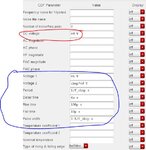
This is the property table for a vpulse source.
I want to set the dc value for my verilog module as like this, so that I can change it based on the simulation (Red). In the meantime the clock transient behavior will remain same (Blue).
 

This is the property table for a vpulse source.
I want to set the dc value for my verilog module as like this,
so that I can change it based on the simulation (Red).
In the meantime the clock transient behavior will remain same (Blue).
Answer is
Code:
parameter real aho = -999.9;
real boke, kasu;

boke = transition(vdd*tgl1, tol, tol, tol);

if($abstime == 0.0)
  kasu = aho;
else
  kasu = boke;

if(analysis("dc", "static"))
  V(ChopClk) <+ aho;
else
  V(ChopClk) <+ kasu;
 
Last edited:

Status
Not open for further replies.

Part and Inventory Search

Welcome to EDABoard.com

Sponsor

Back
Top