Continue to Site

Welcome to EDAboard.com

Welcome to our site! EDAboard.com is an international Electronics Discussion Forum focused on EDA software, circuits, schematics, books, theory, papers, asic, pld, 8051, DSP, Network, RF, Analog Design, PCB, Service Manuals... and a whole lot more! To participate you need to register. Registration is free. Click here to register now.

Driver for steppermotor using Arduino doesn't work

Status
Not open for further replies.

Art24

Newbie level 3
Joined
Jul 17, 2018
Messages
3
Helped
0
Reputation
0
Reaction score
0
Trophy points
1
Activity points
32
Hi everyone,

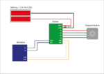
I am fairly new to Arduino and electronics overall. I am trying to make a motorised camera slider using a Nema 17 Steppermotor (42BYGHW609). To work with an Arduino, I am also using a driver (A4988). To get a 12 V input I have connected eight 1.5 V AA batteries in series (meassured output: 12.8 V). I connected everyting like in the picture (exept a decoupeling capacitor of 100 uF) Screenshot_1.jpg

I have soldered everything myself. First it didn't work, but then I noticed that when I twisted or pressed the driver in de breadboard the motor was turning. I thought there was a problem with the breadboard, but when I soldered all the pins directly to the driver it stopped working again.

Does anyone know what could be wrong. Maybe a to low current from the batteries or is the driver defect (I got two and both don't work). Or is it the decoupeling capacitor that has a bigger value?

Thank you in advance!

With kind regards,

Art
 

Hi,

I think - from memory - AAA are about 1440mAh, not sure how deep a momentary discharge can be with such batteries.

Pressed maybe, but twisted an IC in a breadboard? Could have been loose connections and could be that on soldering something burnt or there's a solder bridge somewhere or not any of those. I imagine the step sequence is correct, too.

Maybe a quick way of seeing if the motor and batteries work together is to very quickly connect both windings, one at a time, to the battery terminals and see if the stepper steps at all.

Also, maybe check the current required by each stage on paper/from datasheets and then measure to see if it is sufficient to drive them.
 

Hi,

You know that your circuit is defective.
But you show us another circuit that is correct.

It's the same as if you have two tyres, a good one and a defective one ... and you give the good one for repair.

Show us a photo of your (the defective) circuit.

Klaus
 

I connected the batteries to the motor and saw it rotate a little bit, so I guess it could work properly. Here is a picture I took and a scheme. Hope this will work.

IMG_20180718_105253809.jpgTekengebied 1.png

Art
 

Hi again,

The schematic looks okay.

If you feel sure that you have the step sequence correct and the coil connections are/were correct but find it still not functioning, looking through these kind of web pages can be helpful to look at step/wiring issues; it's just an example, and as you may have seen, each may have a different coil energising sequence so you just have to muddle it out and be patient until at long last the motor works. I think it took me about a full day's misery or more getting a bipolar stepper motor just to start stepping clockwise and then anti-clockwise in single and double steps - after doing a lot of reading as well, of course.

If the issue turns out to be the battery power, another option - if it must be batteries - is to try three 4.5V batteries - they have a fair amount of power and last more than 2 minutes before running out.

I hope you have solved the issue and the circuit is now working.
 

Several aspects to think about:
1.) Motor has 2R impedance, rated 1,7A @3,7V nom. for each phase, so supply of 8V is more than sufficient.
2.) AAA batteries cannot deliver the high current needed for supplying the motor. Voltage will collapse after short operation.
3.) A4988 has chopper operation with senseR to limit motor current. You are using a module, without knowing how it was dimensioned. Seems the module was designed to limit @2A, which overloads stepper (& even more stresses the batteries)

Ok, thank you for pointing that out, what kind of battery do you recommend for me to use? Should it be at least a 8V and 1.7A one (like a 12V lead-acid battery) or should it be exactly those values? I don't really understand point three, is the driver not suited for my project? Sorry I am quite new to elctronics.

Thank you in advance!
 

You should also pay attention to the aspects of ESD inherent to inductive loads, as well as to EMI susceptivity of breadboards and aerial wires such as the ones shown at above picture; wherever possible, twist the wires in pairs with the GND, and make them as short as possible, close to the boards. For the stepper motor and battery, I would suggest increase a bit the wire gauge, due to the high surge current necessary to turn it each step. As rho-bot mentioned above, it is likely this battery has not enough capacity to drive such a peak power.

- - - Updated - - -

Just an additional tip: In parallel with the 100uF capacitor, add one ceramic of about 100nF, as the electrolytic one has an internal series resistance (ESR) that may limit its peak current capacity a little.
 

Ok, thank you for pointing that out, what kind of battery do you recommend for me to use? Should it be at least a 8V and 1.7A one (like a 12V lead-acid battery) or should it be exactly those values? I don't really understand point three, is the driver not suited for my project?
Yes, you should use a battery which is capable of supplying min. 1,7A. A 12V car battery would be sufficient.
Wire gauge paired with long cables is also an issue. shorten cables & increase AWG.

Regarding point 3):
Allegro A4988 is suited for this motor, but you should read the datasheet to understand what needs to be setup properly for operation.
I saw a potentiomenter on your driver module, so I assume it is for setting Vref. If the assumption is correct, by this you can adjust the max. motor current to max. 1.7A
 
Status
Not open for further replies.

Part and Inventory Search

Welcome to EDABoard.com

Sponsor

Back
Top