Continue to Site

Welcome to EDAboard.com

Welcome to our site! EDAboard.com is an international Electronics Discussion Forum focused on EDA software, circuits, schematics, books, theory, papers, asic, pld, 8051, DSP, Network, RF, Analog Design, PCB, Service Manuals... and a whole lot more! To participate you need to register. Registration is free. Click here to register now.

H Bridge Grid Tied Inverter is reasonable despite non-sinusoidal current?

Status
Not open for further replies.
T

treez

Guest
Hello,
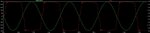
I have done this “poor-person’s” Grid Tied Inverter simulation in LTspice. (Schematic and LTspice simulation are attached, waveform of current supplied back into the mains is also attached)
It puts power back into the mains.
Admittedly, the current waveform is not sinusoidal, though it does have a decent power factor.
The thing is, surely it is not so absolutely massively important for a Grid Tied Inverter to have a purely sinusoidal output waveform? After all, the duty of drawing sinusoidal, in-phase current from the mains rests with the loads, not the inverters. ..And a great many of the loads on the mains draw non-sinusoidal mains current (eg sub 75W SMPS’s in the EU). If all of the loads on a particular mains phase are drawing non-sinusoidal current, then a pure-sinusoidal inverter for that particular phase is a waste of time…….because it simply will not be able to deliver sinusoidal current into that particular mains phase.
So do you agree, that the attached H Bridge inverter is of some good (admittedly not perfect) and can play a role in energy saving by pushing power back into the mains from eg a renewable source?

- - - Updated - - -

Also,
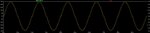
If you do object to the previous version of the H Bridge grid tied inverter,(due to its lack of sinusoidal current) then does the following one please you?...
This H bridge grid tied inverter (attached) pumps a sinusoidal current back into the mains….however it simply does this by having a sinusoidal reference voltage into its pwm controller….there is absolutely none of the complicated control software which exists in all the microcontroller solutions for grid tied inverters. This is an extremely simple grid tied inverter. Admittedly, it is devoid of the rather faster dynamic feedback loop of the usual software based GTI solutions…but in all truth, as long as somebody on the same mains phase is drawing more power than this simple H bridge is pumping back into the mains, then it will operate perfectly well.
So what’s wrong with it?
Why is there a need for GTI’s with reams of complex software control algorithms?
Attached please find the LTspice schematic, schematic and current waveform of this “simple sinusoidal grid tied inverter”
 

Attachments

  • H bridge grid tied inverter.txt
    8.4 KB · Views: 48
  • H Bridge inverter schematic.pdf
    18.2 KB · Views: 108
  • Mains voltage and inverter current.jpg
    Mains voltage and inverter current.jpg
    107.8 KB · Views: 69
  • H Bridge inverter _sinusoidal current _schematic.pdf
    20.1 KB · Views: 120
  • H bridge grid tied inverter_sinusoidal current.txt
    10.8 KB · Views: 54
  • Mains voltage and inverter _sinusoidal current.jpg
    Mains voltage and inverter _sinusoidal current.jpg
    108 KB · Views: 76

And if the previous GTI did not please you, then what about this next one….all this one does is simply sense the output voltage of the inverter, and uses a simple analog error amplifier to make it sinusoidal and in phase with the mains voltage.
…and all this is achieved without using any of the reams of control software that most GTI solutions recommend.
So why are people not using these simple techniques to do GTI’s?
Why must GTIs have so much control software associated with them?...i have just shown that its not always necessary…you can run the simulation (in LTspice) and see for yourself.
For a huge number of applications, the simple GTI methods that I show here would be fine. A superfast dynamic feedback loop using masses of software is just not always needed for a GTI………so why di ti.com and st.com etc etc all advocate reams of control software for GTI’s?
 

Attachments

  • H bridge grid tied inverter_sinusoidal current_regulated_2.txt
    14 KB · Views: 50
  • H Bridge inverter _sinusoidal current _regulated __schematic.pdf
    22.5 KB · Views: 70
  • Mains voltage and inverter _regulated _sinusoidal current.jpg
    Mains voltage and inverter _regulated _sinusoidal current.jpg
    82.5 KB · Views: 72

I made a simulation like a square-wave inverter sending to the grid. I set my inverter to various volt levels.

I installed a current source to produce constant 1A. To match your waveform in post #1, the current source needs to generate a sinewave.

If I make a plain square wave, then I find uncontrollably high Amperes go out at every point in the cycle when the mains sine voltage is lower than mine.

And I find I must not set my inverter less than 170V, because that is when mains AC peak surpasses mine and I am destroyed.
 

Your analog GTI controller implements only part of the required functionality. It misses derivation of the sine reference from mains voltage, output current control according to the available source power. Also safety and self protective features like anti-islanding, over current & over voltage protection.

Let's re-evaluate your claim of simple analog versus complicated digital control after seeing the full implementation.
 
  • Like
Reactions: treez

    T

    Points: 2
    Helpful Answer Positive Rating
Hello there, we have done GTI's in analog and digital, if the inverter is not properly synch'd to the mains then it will draw reactive power i.e.extra amps you don't want,

Ideally you have a soft start and control the amount of current you inject to the mains - plus you must not inject more than 5mA DC to meet standards (earth stake corrosion) - you want to inject a very clean sine wave if you can - so that lots of GTI's don't distort the mains ...

Then (per FvM) you have to detect when the mains goes away (anti -islanding), so that you are not trying to back feed the grid and electrocute some service personnel ...

So simple doesn't really cut it for a commercial product ...
 
  • Like
Reactions: treez

    T

    Points: 2
    Helpful Answer Positive Rating
I do digitally controlled amplifiers and the FPGA code controlling it (and have been vaguely contemplating a digitally controlled bidirectional PFC)

Digital does have real downsides (timing resolution, bandwidth, ADC limitations or expense) but once you get your analog signals into the digital world with sufficient resolution and bandwidth additional functionality is 'easy' to add.

Consider that things like +, -, 'if-then-else' are trivial in the digital world but take actual hardware in the analog world. The types of requirements for a grid tied inverter that other's have mentioned would baloon the hardware substantially if done in analog.


Though not familiar with the software you're talking about specifically I'd suggest that at its core the digital control is quite the same as analog. You have a reference, measurement and error amplifier. Digital control techniques (like IIR) are exactly analogous to their analog counterparts.
 
  • Like
Reactions: d123 and treez

    T

    Points: 2
    Helpful Answer Positive Rating

    d123

    Points: 2
    Helpful Answer Positive Rating
It misses derivation of the sine reference from mains voltage, output current control according to the available source power. Also safety and self protective features like anti-islanding, over current & over voltage protection.
Thanks yes i agree i would need them, but again woudl not need vast amounts of software to do them....i would derive the sine reference from the mains itself.
I didnt show all the protection functions for the sake of clarity and brevity.

The lack of software engineers these days i reckon means an analog solution has a lot going for it....i mean, the digital software solution is like as follows
https://www.ti.com/tool/TMDSSOLARUINVKIT

...and not many people can program a piccolo microcontroller to do a GTI.

All the protection functions mentioned in this post seem simple to do in analog....i agree it would make a slightly bigger solution, but tiny size doesnt really matter too much with a GTI....as you know its not portable or fashion equipment.

- - - Updated - - -

if the inverter is not properly synch'd to the mains then it will draw reactive power i.e.extra amps you don't want,
We would sync it by gernerating the sinusoidal reference from the mains itself.

- - - Updated - - -

Ideally you have a soft start and control the amount of current you inject to the mains
Yes we can control the current injected by varying the amplitude of the sinusoidal reference, and can as you know, easily do this in analog.

- - - Updated - - -

if the inverter is not properly synch'd to the mains then it will draw reactive power i.e.extra amps you don't want,
Thanks yes, but if its only slightly un-sync'd then still i doubt it matters too much...since as we know, there are loads of sub 75W loads on the mains which draw lots of reactive power...so a slightly un-sync'd inverter is surely not going to be soaked in the guilt of this?
 

The lack of software engineers these days i reckon means an analog solution has a lot going for it
...and not many people can program a piccolo microcontroller to do a GTI.
This sounds like the essential of your thread, make it analog because you don't manage the digital implementation. I really appreciate good analog design, that's where I come from. But these days, many control functions can be implemented easily and more economic in the digital domain. You can't however successfully write the software without understanding the control algorithm which is analog by nature.
 
Simple H-bridge automatically pushes correct polarity and correct phase back into grid.

Mains provides bias to H-bridge. The zener diodes are not absolutely necessary but they reduce wastage. If they are omitted then shoot-through occurs at certain times in the cycle.

grid-tied inverter 171V simple H-bridge transis biased by mains AC.png

Notice the right-hand scope traces indicate that the Ampere waveform is 180 deg out of phase to mains voltage, which means my 171VDC supply is pushing current out to the grid, in perfect sync to the grid waveform.

During blackout, the H-bridge shuts off, thus islanding me.
 

At first glance there will be considerable heating of the xtors, they are acting under current gain, i.e. not fully on. Much like using a class AB power amplifier to feed power to the mains - you can do it - but the xtors will get hot ...
 

This simulation is slightly different from my above schematic because it has a series LC which creates its own reactive impedance thus reducing heat buildup in other components.

grid-tied inverter 150V LC series H-bridge transis biased by mains AC.png

In this design my supply can be less than 170 VDC. The series LC shapes the waveform into a sine, at the same time it boosts the peak voltage.

The L & C values need experimentation, to deliver a sine shape. The capacitor needs to be non-polarized.
 
  • Like
Reactions: treez

    T

    Points: 2
    Helpful Answer Positive Rating
it would be interesting to plot the voltage across one of the xtors and the current thru it ...

- - - Updated - - -

also interesting to see would be if the L-C was sized to be resonant at 60Hz...
 

Status
Not open for further replies.

Similar threads

Part and Inventory Search

Welcome to EDABoard.com

Sponsor

Back
Top