Continue to Site

Welcome to EDAboard.com

Welcome to our site! EDAboard.com is an international Electronics Discussion Forum focused on EDA software, circuits, schematics, books, theory, papers, asic, pld, 8051, DSP, Network, RF, Analog Design, PCB, Service Manuals... and a whole lot more! To participate you need to register. Registration is free. Click here to register now.

Ferrite core inverter

Status
Not open for further replies.

NIDHINDAS

Newbie level 6
Joined
Sep 30, 2010
Messages
12
Helped
0
Reputation
0
Reaction score
1
Trophy points
1,283
Activity points
1,398
hi friends ,

Like this can we convert 320 dc to 230 ac 50 hz by not using bulky iron core transformer ? my plan is to use ferrite core or toroidal transformer .

Ferrite core is for high frequency use only ?,From where i can get data which type of core can use for 50hz , I have EE-50 core can i use that one ?

pls help.
 

DC to AC conversion is not possible using only a transformer. You need to use PWM to modulate a square wave (high frequency) into a 50Hz AC.
 

It's not clear what you want to achieve. No transformer needed to convert 320 VDC to 230 VAC, just a full bridge.
 

stage02.png

hi FVM ,

let me make very clear to you , i need conversion from DC to AC.

It is not possible to convert 320 DC to 230 AC by using rectifier we need inverter mechanism for that.

one common method is use H-bridge drive driven by 50 hz and connect bulky iron core transformer and just convert which i don't want .

other is 320 DC is chopped with 20 khz fed to mosfet and to ferrite core transformer and get 230 AC (high frequency) out , same method i need to use but needs output 50 hz-60hz only .

Design image is attached
 

hi bradtheRad,

yes the same i need to use , but i can use only high frequency transformer (Ferrite /Toroidal) .
so need to drive H-bridge with modulated SPWM at 20 khz
and my question is how to get 50 /60 Hz from output ?, Is there any filtering mechanism without
creating much load .

stage02.png
 
You need to use a base frequency of 20kHz -50kHz and use PWM to modulate that at 50/60Hz.

Your transformer need to be designed for 20kHz-50kHz operation and not 50/60Hz.

No need to rectify the output but use a low pass filter to remove the baseband frequency. If you are using a centre-tapped secondary, ground the centre tap.

This is how radios work. Feedback control will be tricky but possible.
 

No need to rectify the output but use a low pass filter to remove the baseband frequency. If you are using a centre-tapped secondary, ground the centre tap.

This is how radios work. Feedback control will be tricky but possible.

Is this type of low pass filter will have any impact on % of inductor / resistor load connected ? if yes how it can be taken care

I think to give optically isolated feed-back from 230 VAC is to controller for Duty cycle modification.This can stabilize the output.

Any further suggestion
 

Is this type of low pass filter will have any impact on % of inductor / resistor load connected ?

If the base frequency is 50kHz and the modulation is 50Hz, you can very easily remove the carrier with a small power inductor and that may have only a marginal effect on the load.

A real design needs meaningful calculations at every stage.
 
can we convert 320 dc to 230 ac 50 hz

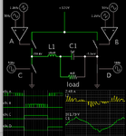
This schematic portrays the usual method using a full H-bridge with SPWM.

2 opamps SPWM 320VDC H-bri LC 2nd-ord load gets 230VAC sine.png

Notice my screenshot shows clock 'A' switching rapidly. Switch D conducts during this half of the cycle.
B & C are off right now.

The switches are replaced by transistors or mosfets in real life.

The L & C create a second-order low-pass filter. This is the type commonly used to smooth SPWM. My values are suitable for a 1200 Hz carrier and 50 Hz fundamental.
The load gets AC sinewaves.
Notice the inductor must handle several Amperes, even though the final load is about 500 mA.
 
which is this tool used for simulation ? and if the load is inductive will it have any impact on LC filter?
 

which is this tool used for simulation ? and if the load is inductive will it have any impact on LC filter?

It's Falstad's animated interactive simulator. Free to download and use:

www.falstad.com/circuit

If the load is inductive or capacitive then it affects power factor. If this creates an error which causes a problem, then you need to consider how to correct it. If you don't then your load tries to draw current at wrong times in the AC cycle.
 
Status
Not open for further replies.

Part and Inventory Search

Welcome to EDABoard.com

Sponsor

Back
Top