Continue to Site

Welcome to EDAboard.com

Welcome to our site! EDAboard.com is an international Electronics Discussion Forum focused on EDA software, circuits, schematics, books, theory, papers, asic, pld, 8051, DSP, Network, RF, Analog Design, PCB, Service Manuals... and a whole lot more! To participate you need to register. Registration is free. Click here to register now.

ASCO circuit optimizer usage issue

Status
Not open for further replies.

promach

Advanced Member level 4
Joined
Feb 22, 2016
Messages
1,199
Helped
2
Reputation
4
Reaction score
5
Trophy points
1,318
Activity points
11,636
View attachment inv.zip

I am facing the following error when using asco circuit optimizer for a simple CMOS inverter.

Could anyone help ?

[phung@archlinux inv]$ asco-test -ngspice inv.sp

ASCO-0.4.10 - Copyright (c) 1999-2016 Joao Ramos
This program is distributed in the hope that it will be useful,
but WITHOUT ANY WARRANTY; without even the implied warranty of
MERCHANTABILITY or FITNESS FOR A PARTICULAR PURPOSE. See the
GNU General Public License for more details.

INFO: ngspice initialization on 'archlinux'
INFO: Initialization has finished without errors
DEBUG: evaluate.c - Executing errfunc
INFO: evaluate.c - altermc=2
DEBUG: errfunc.c - Step1
DEBUG: errfunc.c - Step2
DEBUG: errfunc.c - Step3
DEBUG: errfunc.c - Step4
errfunc.c - WriteToMem -- Data not read for measurement in *.cfg: ROUT
INFO: auxfunc_measurefromlis - WriteStats -- Data was not read for ZROUT0.
DEBUG: errfunc.c - Step7
INFO: errfunc.c - Step7 -- altermc=2
DEBUG: errfunc.c - Step8
DEBUG: evaluate.c - Leaving errfunc
INFO: evaluate.c - altermc=0
DEBUG: evaluate.c - Executing errfunc
INFO: evaluate.c - altermc=0
DEBUG: errfunc.c - Step1
DEBUG: errfunc.c - Step2
DEBUG: errfunc.c - Step3
DEBUG: errfunc.c - Step4
DEBUG: errfunc.c - Step7
DEBUG: errfunc.c - Step8
DEBUG: evaluate.c - Leaving errfunc
INFO: evaluate.c - altermc=0
[phung@archlinux inv]$


inv.cfg

Code:
#Optimization Flow#
Alter:yes           $do we want to do corner analysis?
MonteCarlo:no       $do we want to do MonteCarlo analysis?
AlterMC cost:3.00   $point at which we want to start ALTER and/or MONTECARLO
ExecuteRF:no        $execute or not the RF module to add RF parasitics?
SomethingElse:      $
#


#DE#
choice of method:3
maximum no. of iterations:50
Output refresh cycle:2
No. of parents NP:10
Constant F:0.5
Crossover factor CR:1
Seed for pseudo random number generator:3
Minimum Cost Variance:1e-6
Cost objectives:10
Cost constraints:10000
#


# ALTER #
.control 
*alter vdd=[2.0 2.1 2.2]
run
.endc
*.protect
*.inc [../models/cmos035_slow.mod ../models/cmos035_typ.mod ../models/cmos035_fast.mod]
*.unprotect
*.temp [-40 +25 +85]
.param
+    V_SUPPLY=[2.0 2.1 2.2]
*.protect                                                $ As much as 6 variables can be swept at the same time.
*.lib hl49ciat57k5r200.mod [mos_wcs mos_nom mos_bcs]     $ Format is [a] or [a b] or ... [a b c d e f] =>1 space
*.unprotect                                              $ and not :[ a], [a ], [ a ] => space is not really necessary
*.temp [-40 +25 +85]                                     $ and not :[a  b]            => only 1 ' ' between 'a' and 'b'
*.param                                                  $ Add '*' to skip a line
*+    vddd=[2.25 2.50 3.30]                              $
*+    kc=[0.95 1.05]:LIN:10        $ LIN not yet implemented
*+    kr=[0.87 1.13]:LOG:10        $ LOG not yet implemented
*+    Ierror=[0.7 1.3]
*+    k00=[0 1]
*+    k01=[0 1]
*+    k02=[0 1]
*+    k03=[0 1]
*+    k04=[0 1]
*+    k05=[0 1]
*+    k06=[0 1]
*+    k07=[0 1]
*+    k08=[0 1]
*+    k09=[0 1]
#


#Monte Carlo#
NMOS_AVT:12.4mV           $ This values will be divided by sqrt(2) by the program
NMOS_ABETA:7.3%           $ 'm' parameter is taken into account
PMOS_AVT:10.9mV           $
PMOS_ABETA:3.7%           $
SMALL_LENGTH:0.0u         $ Small transistors if l<= SMALL_LENGTH
SMALL_NMOS_AVT:20mV       $ Small transistors parameters
SMALL_NMOS_ABETA:10%      $
SMALL_PMOS_AVT:10mV       $
SMALL_PMOS_ABETA:5%       $
R_DELTA:0.333%            $ Resistors matching at 1 sigma between two resistors
L_DELTA:0.333%            $ Inductors matching at 1 sigma between two inductors
C_DELTA:0.333%            $ Capacitors matching at 1 sigma between two capacitors
#


# Parameters #
Supply voltage:#V_SUPPLY#:2.0:0:0:LIN_DOUBLE:---
Temperature:#TEMP#:25:0:0:LIN_DOUBLE:---
Minimal gate length:#LMIN#:0.35u:0:0:LIN_DOUBLE:---
Input frequency:#INP_FREQ#:850E6:0:0:LIN_DOUBLE:---
PMOS width:#WP#:10000u:1m:10m:LIN_DOUBLE:OPT
*Output voltage:#V_OUT#:1:1:5:LIN_DOUBLE:---
#


# Measurements #
*P_SUPPLY:---:MIN:0
ROUT:OUT:GE:60E3
#


# Post Processing #
#


#this is the last line


inv.sp

Code:
*CMOS inverter http://electronics.stackexchange.com/questions/383552/measurement-of-output-impedance-of-a-cmos-inverter

.PARAM V_SUPPLY = '#V_SUPPLY'
*.PARAM INP_FREQ = '#INP_FREQ#'
*.PARAM INP_PERIOD = '1/INP_FREQ'
*.PARAM NO_PERIODS = '4'
*.PARAM TMEAS_START = '(NO_PERIODS-1)*INP_PERIOD'
*.PARAM TMEAS_STOP = '(NO_PERIODS)*INP_PERIOD'
.PARAM AC_POINTS = 10
.PARAM AC_START = 1000
.PARAM AC_STOP = 1E6

*** *** SUPPLY VOLTAGES *** ***
VDD VDD 0 {V_SUPPLY}
VSS VSS 0 0

*** *** INPUT SIGNAL *** *** 
** VSIG IN VSS 0
** VSIG IN VSS AC 1 DC 0
** VSIG IN VSS AC 1 DC 'V_SUPPLY/2'

*** *** CIRCUIT UNDER TEST *** ***
MP OUT IN VDD VDD P1 W='#WP#' L=#LMIN#
MN OUT IN VSS VSS N1 W='#WP#/2' L=#LMIN# 

** CL OUT VSS 3p
** RIN IN VSS 1G

CIN IN VSS 1
Rf OUT IN 1E15
** Lf OUT IN 1E-15
** The input can be either biased with a DC source, or a DC feedback circuit. Using a DC feedback circuit (RC, inductor, whatsoever) makes only sense if there's no DC voltage source, see https://www.edaboard.com/showthread.php?377214-Noise-in-CMOS-Inverter&p=1617292&viewfull=1#post1617292  


*** *** ROUT TEST SIGNAL WITH FIXED 1A CURRENT *** ***
** this is a way to measure or plot the current source IOUT in spice using 0V voltage source
VOUT OUT VOUT 0
*VOUT VOUT 0 '#V_OUT#'
*** *** IOUT flows into the output of the circuit under test, so negative terminal node of this current source is OUT instead of VSS
IOUT VSS VOUT AC 1
*IOUT OUT VOUT AC 1


*** *** ANALYSIS *** ***
.AC dec 'AC_POINTS' 'AC_START' 'AC_STOP'
*.TRAN 'INP_PERIOD/1000' 'NO_PERIODS*INP_PERIOD'
*
*.PROBE TRAN V(IN)
*.PROBE TRAN V(OUT)
.OPTION POST PROBE ACCURATE
.include modelcard.nmos
.include modelcard.pmos

*.control
*AC dec 'AC_POINTS' 'AC_START' 'AC_STOP'
*AC dec 10 1000 1E6

*let ROUT=OUT/abs(i(VOUT))
*plot ROUT
*print ROUT > ROUT.log
*.endc

.END


extract/ROUT

Code:
# Info #
Name:ROUT
Symbol:ZROUT
Unit:Ω
Analysis type:AC
Definition:Output Impedance
Note:
#

# Commands #
.measure AC #SYMBOL# rms par('v(OUT)/abs(i(VOUT))')
*.MEASURE AC #SYMBOL# rms par('abs(i(vdd)*3)')
#
 

finally I made inv.sp passed asco-test. See attached the zip file. View attachment inv.zip

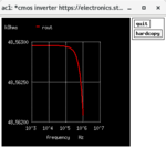
I added the objective on ac_power in inv.cfg as well as fixing the syntax mistake on "V_SUPPLY" in inv.sp

However, from the .out file, I have zrout1 = 0.00000e+00 from= 1.00000e+03 to= 1.00000e+06

Running ngspice inv.net does not give me any impression of zero impedance though.

Screenshot from 2018-07-18 16-28-49.png

Did I miss anything else in the inv.cfg file ?

inv.net

Code:
*CMOS inverter https://electronics.stackexchange.com/questions/383552/measurement-of-output-impedance-of-a-cmos-inverter

.PARAM V_SUPPLY = 3.3
.PARAM V_OUT = 2
*.PARAM INP_FREQ = '#INP_FREQ#'
*.PARAM INP_PERIOD = '1/INP_FREQ'
*.PARAM NO_PERIODS = '4'
*.PARAM TMEAS_START = '(NO_PERIODS-1)*INP_PERIOD'
*.PARAM TMEAS_STOP = '(NO_PERIODS)*INP_PERIOD'
.PARAM AC_POINTS = 10
.PARAM AC_START = 1000
.PARAM AC_STOP = 1E6

*** *** SUPPLY VOLTAGES *** ***
VDD VDD 0 'V_SUPPLY'
VSS VSS 0 0

*** *** INPUT SIGNAL *** *** 
** VSIG IN VSS 0
** VSIG IN VSS AC 1 DC 0
** VSIG IN VSS AC 1 DC 'V_SUPPLY/2'

*** *** CIRCUIT UNDER TEST *** ***
MP OUT IN VDD VDD P1 W=2U L=2U
MN OUT IN VSS VSS N1 W=1U L=2U 

** CL OUT VSS 3p
** RIN IN VSS 1G

CIN IN VSS 1
Rf OUT IN 1E15
** Lf OUT IN 1E-15
** The input can be either biased with a DC source, or a DC feedback circuit. Using a DC feedback circuit (RC, inductor, whatsoever) makes only sense if there's no DC voltage source, see https://www.edaboard.com/showthread.php?377214-Noise-in-CMOS-Inverter&p=1617292&viewfull=1#post1617292  


*** *** ROUT TEST SIGNAL WITH FIXED 1A CURRENT *** ***
** this is a way to measure or plot the current source IOUT in spice using 0V voltage source
VOUT OUT VOUT 0
*** *** IOUT flows into the output of the circuit under test, so negative terminal node of this current source is OUT instead of VSS
IOUT VSS VOUT AC 1

*** *** ANALYSIS *** ***
*.AC dec 'AC_POINTS' 'AC_START' 'AC_STOP'
*.TRAN 'INP_PERIOD/1000' 'NO_PERIODS*INP_PERIOD'
*
*.PROBE TRAN V(IN)
*.PROBE TRAN V(OUT)
.OPTION POST PROBE ACCURATE
.include modelcard.nmos
.include modelcard.pmos

.control
*AC dec 'AC_POINTS' 'AC_START' 'AC_STOP'
AC dec 10 1000 1E6

let ROUT=v(OUT)/abs(i(VOUT))
plot ROUT
print ROUT > ROUT.log
.endc

.END


inv.cfg

Code:
#Optimization Flow#
Alter:no           $do we want to do corner analysis?
MonteCarlo:no       $do we want to do MonteCarlo analysis?
AlterMC cost:3.00   $point at which we want to start ALTER and/or MONTECARLO
ExecuteRF:no        $execute or not the RF module to add RF parasitics?
SomethingElse:      $
#


#DE#
choice of method:3
maximum no. of iterations:50
Output refresh cycle:2
No. of parents NP:10
Constant F:0.5
Crossover factor CR:1
Seed for pseudo random number generator:3
Minimum Cost Variance:1e-6
Cost objectives:10
Cost constraints:10000
#


# ALTER #
*.protect
*.inc [../models/cmos035_slow.mod ../models/cmos035_typ.mod ../models/cmos035_fast.mod]
*.unprotect
*.temp [-40 +25 +85]
.param
+    V_SUPPLY=[2.0 2.1 2.2]
*.protect                                                $ As much as 6 variables can be swept at the same time.
*.lib hl49ciat57k5r200.mod [mos_wcs mos_nom mos_bcs]     $ Format is [a] or [a b] or ... [a b c d e f] =>1 space
*.unprotect                                              $ and not :[ a], [a ], [ a ] => space is not really necessary
*.temp [-40 +25 +85]                                     $ and not :[a  b]            => only 1 ' ' between 'a' and 'b'
*.param                                                  $ Add '*' to skip a line
*+    vddd=[2.25 2.50 3.30]                              $
*+    kc=[0.95 1.05]:LIN:10        $ LIN not yet implemented
*+    kr=[0.87 1.13]:LOG:10        $ LOG not yet implemented
*+    Ierror=[0.7 1.3]
*+    k00=[0 1]
*+    k01=[0 1]
*+    k02=[0 1]
*+    k03=[0 1]
*+    k04=[0 1]
*+    k05=[0 1]
*+    k06=[0 1]
*+    k07=[0 1]
*+    k08=[0 1]
*+    k09=[0 1]
#


#Monte Carlo#
NMOS_AVT:12.4mV           $ This values will be divided by sqrt(2) by the program
NMOS_ABETA:7.3%           $ 'm' parameter is taken into account
PMOS_AVT:10.9mV           $
PMOS_ABETA:3.7%           $
SMALL_LENGTH:0.0u         $ Small transistors if l<= SMALL_LENGTH
SMALL_NMOS_AVT:20mV       $ Small transistors parameters
SMALL_NMOS_ABETA:10%      $
SMALL_PMOS_AVT:10mV       $
SMALL_PMOS_ABETA:5%       $
R_DELTA:0.333%            $ Resistors matching at 1 sigma between two resistors
L_DELTA:0.333%            $ Inductors matching at 1 sigma between two inductors
C_DELTA:0.333%            $ Capacitors matching at 1 sigma between two capacitors
#


# Parameters #
Supply voltage:#V_SUPPLY#:2.0:0:0:LIN_DOUBLE:---
Temperature:#TEMP#:25:0:0:LIN_DOUBLE:---
Minimal gate length:#LMIN#:0.35u:0:0:LIN_DOUBLE:---
Input frequency:#INP_FREQ#:850E6:0:0:LIN_DOUBLE:---
PMOS width:#WP#:10000u:1m:10m:LIN_DOUBLE:OPT
#


# Measurements #
*P_SUPPLY:---:MIN:0
*VHIGH:OUT:GE:1.95
*VLOW:OUT:LE:0.05
ac_power:OUT:MIN:0
ROUT:OUT:GE:60E3
#


# Post Processing #
#


#this is the last line
 

Status
Not open for further replies.

Similar threads

Part and Inventory Search

Welcome to EDABoard.com

Sponsor

Back
Top