Continue to Site

Welcome to EDAboard.com

Welcome to our site! EDAboard.com is an international Electronics Discussion Forum focused on EDA software, circuits, schematics, books, theory, papers, asic, pld, 8051, DSP, Network, RF, Analog Design, PCB, Service Manuals... and a whole lot more! To participate you need to register. Registration is free. Click here to register now.

Level shifting using transistor

Status
Not open for further replies.

gauravkothari23

Advanced Member level 2
Joined
Mar 21, 2015
Messages
640
Helped
5
Reputation
10
Reaction score
4
Trophy points
1,298
Activity points
6,922
Hi all,
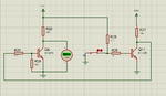
i have made a small circuit which work properly in stimulation but when tested pratically it does not work. (Circuit Diagram attached).
Its just a small circuit which i made it for a basic knowledge of level shifting.
m problem is when the switch is close, R25 shows me 24V but after R25 and at base of Q8, i dont get any voltage due to which the transistor does not gets on. and collector emitter voltage always remains 5V.
the transistor Q11 works properly, it gets ON and OFF when swtich is triggered accordingly.
Can anybody please let me know what the issue is with the circuit.
 

Attachments

  • Level shifter.png
    Level shifter.png
    38.6 KB · Views: 77

If you are seeing 24V at the left side of R25 then no current is flowing into the base. Either the transistor is faulty or it is not connected correctly.


Bob
 

If you are seeing 24V at the left side of R25 then no current is flowing into the base. Either the transistor is faulty or it is not connected correctly.


Bob

you mean to say i need to replace Q8...
but anyhow if Q8 is faulty, atleast it should show some voltage at base. or if it should does't, then please let me know why base voltage does not change if Q8 is faulty.
 

This is misleading: the voltage on the LEFT side of R25 should be about 1.95V when the switch is closed and about 0.05V when the switch is open.

On Q8 the collector to emitter voltage should be about 0.04V with the switch open and 5V when it is closed.

Brian.
 

You should check the connections first.

Bob
 

Hi,

My opinion:
The circuit is over complicated:
The swith voltage is 0V/1V.
At the collector of Q11 it is about 1.8V/0V
And at the collector of Q8 it is 0V/5V

It makes no sense to run Q11 from 24V, it makes no sense to use two BJTs. In my eyes it makes no sense to use any BJT.
The switch with a pullup resistor (= 2 parts) should be sufficient.

In either case: please draw the signal flow from left to right.
(In your case it starts at the center, runs to the must right side, then to the most left side and ends at the center)

Klaus
 

Status
Not open for further replies.

Similar threads

Part and Inventory Search

Welcome to EDABoard.com

Sponsor

Back
Top