Continue to Site

Welcome to EDAboard.com

Welcome to our site! EDAboard.com is an international Electronics Discussion Forum focused on EDA software, circuits, schematics, books, theory, papers, asic, pld, 8051, DSP, Network, RF, Analog Design, PCB, Service Manuals... and a whole lot more! To participate you need to register. Registration is free. Click here to register now.

SMPS Regulation Zeners

Status
Not open for further replies.

Dimitrisvlamis

Member level 2
Joined
Dec 12, 2017
Messages
42
Helped
1
Reputation
2
Reaction score
1
Trophy points
8
Activity points
366
Hello everyone :)

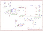
I am currently working in this SMPS which works perfect except the regulation part. I found a schematic on the internet that is almost idetical to mine but the voltage is not 380VDC but 220VDC. The circuit is this and it works as far as i know! Screenshot (3).png

The problem i have is i need to regulate the voltage to 380V and i used 3 diodes of 1.3W each 2 180V And 1 20V to achieve that, with the same optocoupler. My schematic is this : Capture.JPG

How can i calculate the correct resistor value? I have a big margin in voltage, it goes from 400v @10v input and goes till 600V at 15-16V input. Can someone help me with this? Maybe i use small zeners? Maybe a wrong optocoupler?

Thanks in advance
 

What matters is the current through the LED in the optocoupler, not the voltage.
Using Zener diodes like that is OK but you probably want to use ones adding up to slightly less than 380V so there is still current flowing through the opto and it's series resistor when 380V is present at the output.

Calculate the resistor so the current through it is suitable for the PC817 (typically 10mA to 20mA). So for example if the Zeners drop 360V (2 x 180) and the PC817 drops 1.7V, the remaining drop at say 10mA will be in the resistor:

(380V(wanted) - 360V(in Zeners) - 1.7V(in opto)) / 0.01A (opto current) = 1.83K.

If it is regulating properly, the voltage should be stable and never reach more than 380V.

Brian.

Thanks for the quick answer and explaination, so that means i will keep 2 zeners 180 in series, but the current should be 10mA, since my zeners are 1.3W max current is around 7.5mA, so i should change them with 5W version ones right? :)

Also, the fact that my voltage goes around 600V without regulation is not a problem right?
 
Last edited:

Also, the fact that my voltage goes around 600V without regulation is not a problem right?

Well the simple fact is that if your regulation fails the opto will blow up if that's what you're wondering. If the regulation works its all good...

It's wise to have some sort of failsafe since the nature of negative feedback is that any failure causes the output to pin to the positive rail...however the reality is that many circuits don't have such a protection.

Am I correct that this is an on/off type control scheme? If that's the case you could replace the resistor with a current regulator/limit set to 10-20mA. That would also 'sharpen' the turn on and therefore regulation. I like this depletion mosfet current limit circuit:
https://ixapps.ixys.com/DataSheet/98704.pdf
 
  • Like
Reactions: CataM and d123

    d123

    Points: 2
    Helpful Answer Positive Rating

    CataM

    Points: 2
    Helpful Answer Positive Rating
Well the simple fact is that if your regulation fails the opto will blow up if that's what you're wondering. If the regulation works its all good...

It's wise to have some sort of failsafe since the nature of negative feedback is that any failure causes the output to pin to the positive rail...however the reality is that many circuits don't have such a protection.

Am I correct that this is an on/off type control scheme? If that's the case you could replace the resistor with a current regulator/limit set to 10-20mA. That would also 'sharpen' the turn on and therefore regulation. I like this depletion mosfet current limit circuit:
https://ixapps.ixys.com/DataSheet/98704.pdf

Ok so the regulation didnt work haha i burned 2 zeners, 1 opto and 1 resistor (at least not the mosfets again hahah) anyway, i dont have time to wait for the constant current source mosfet thingie because i cant find in my local stores, so i came up with this solution? I have a winding at my transformer around 15v, so if i rectify it and feed it to this circuit to drive the opto in the output of the comparator, you think it will be ok? its a simple voltage comparator with a constant voltage source. dsadadasda.JPG
 

Hi,

That's not a comparator, it's an op amp (...tan tan taaan!).

Replacing the LM358 with a proper comparator IC and a pullup to the 15V from the transformer is probably a nicer version than with an op amp, and comparators are available everywhere and cheap.

I personally feel you are wasting about 2 or even 3 mA current for the TL431. The rest looks okay/right. I'd suggest maybe breaking that 1M down into 5 200k or 10 100k but that will come with a resistor PD penalty. One sole resistor and ~380V and a (by comparison) flimsy little comparator or op amp seems carelessly risky and ill-thought out. Otherwise, great.

Fristly, i was going to use a comparator, i did this because i couldnt find any rail to rail comparator in my spice libraries, so there's not need for this irony :smile: .
and secondly, i dont see where the problem is with using 2 resistors to devide the voltage, what is the ill-thought out situation in this? could you explain?
 

Hi,

Okay. But you get it don't you? - the dreaded "That's not a comparator." comment ;).

I understand that it is better to divide such large voltages between several resistors in case one resistor goes short (yes, yes, open fault more likely but anyway) so as not to put all ones eggs in one basket.


So after all these things i looked and read, i think this is a functional circuit (always talking about the feedback). In theory and simulations it works fine.
What do you think? :)

Schematic_2-7-2018_Sheet-1_20180711144042.png
 

Hi,

Sorry, late answer, busyish day. It would be dishonest to pretend to undestand the whole of your SMPS circuit... The comparator bit looks fine. Personal predilection is for the LM193/ LM2903 or the LM1/2/339 or LM2901 set if wide supply voltage required. Have you considered - if it doesn't affect the voltage divider and works - using a Zener in parallel to the 70k, maybe 2.7V or 2.8V, or say 3V or 3.3V, etc. for sufficient margin to avoid false triggering and as a protection device? Maybe not workable in reality.
 

Well on a closer look of the controller nothing about it is 'intended' for this type of on/off comparator control. It has a standard error amp configured for standard compensation.

So given that I'll point out that this circuit could use the most common isolated feedback mechanism: a compensated TL431 driving an opto directly. This would be 'proper' regulation with none of the comparator bang-bang on/off action.

Also I'll note that the TL431 if uncompensated will also act exactly as a comparator:
Vin>2.5V -> TL431 conducts (down to ~2.5V)
Vin<2.5V -> TL431 is 'open'.

Granted it isn't as quick as a comparator (since it's basically an opamp with a built in reference), but I thought it worth noting.


Finally the only reason I see that old circuit failed is a delay between the opto turning on and the controller reducing its duty cycle sufficiently. Hence it went over-voltage. I don't think this comparator will solve that, though I do think it will at least protect the opto. You might want a potentiometer in the resistor divider so you can trim things and perhaps start by targeting a much lower voltage.
 

Status
Not open for further replies.

Similar threads

Part and Inventory Search

Welcome to EDABoard.com

Sponsor

Back
Top