Continue to Site

Welcome to EDAboard.com

Welcome to our site! EDAboard.com is an international Electronics Discussion Forum focused on EDA software, circuits, schematics, books, theory, papers, asic, pld, 8051, DSP, Network, RF, Analog Design, PCB, Service Manuals... and a whole lot more! To participate you need to register. Registration is free. Click here to register now.

Thermocouple amplifier problem

Status
Not open for further replies.

abdoalghareeb

Member level 5
Joined
Feb 5, 2010
Messages
83
Helped
1
Reputation
2
Reaction score
1
Trophy points
1,288
Activity points
1,974
this is my design for Thermocouple K-type amplifier
The output (TC) of amplifier circuit is connected to ADC0 PORT of ATMEGA8L
At first : To calibrate the amplifire (LT1012) I remove the microcontroller then I short the Thermocouple input to ground , then I adjust the offset
potentiometer(R1) to make the output of amplifier circuit equal zero .
now I insert the microcontroller and the problem appears here , about 100 mv appears on ADC0 port (it should be stay zero).
Why does this millivolt appear?
123.png
 

Hi,

My thoughts.
Please mind: Low impedance signals are good, because they are stable, reliable and they are not prone to pick up errors like noise or leakage currents.
A thermocouple signal is a low impedance signal. A good signal.
But the first you do is to connect a series resistor of 10k.... this makes the signal weak....and prone to errors.
The same is with the Opamp output.

The first I'd do is to make both parhs more low impedance. Maybe 100R.
***
For sure this influences the filters you built.
Let's analyze them:
R23 / C18 form a low pass with tau = 100ms
R2 / C20 --> tau = 10 ms
R25 / C26 --> tau = 1000ms
Three different frequencies. Is there a reason?

I personally don't like electrolytic capacitors as filter capacitors. They are not suitable because they suffer from leakage currents and are not suitable for higher frequencies.
Now you may say there are no high frequencies. Only partly correct, because the ADC within the microcontroller causes current peaks at every conversion. These short peaks call for a fast capacitor.

My recommendation:
Use 100R / 100nF at the input and 100R / 100nF from Opamp to ADC. Both filters are just for noise suppression.
Then use the 1000ms filter at the Opamp feedback. But no electrolytics capacitor. This is the true signal LPF.

Best filter capacitors are foil capacitors, but here - because you don't process audio data - you could use ceramics capacitors.
They suffer from poor linearity, but with your DC style signal this should cause no problem.

Microcontroller:
Be sure to switch OFF the port pullup feature at the ADC inputs.
Switch the port as ADC input and leave it in this state.

Some additional hints:

My personal taste: I'd rather use a 100ms analog filter and add the 100ms filter as a software filter.

ARef: I'd replace the (slow) electolytics with a 1uF ceramics capacitor. I assume it results in better VRef stability.

AVcc: I don't like undamped LC filters. They cause a high Q resonance. I'd rather replace the L with an 100R and the C with a 1uF ceramics.

Klaus
 
Yes, R25 is the main cause of the voltage drop. ADC inputs aren't super-high impedance and draw charge on every sample. If you change that as Klauss suggested I think you'll see the majority of this specific issue go away.

A couple other comments:
-That's a good amplifier but there are lower offset choices out there (zero drift) and:
-A different amplifier could eliminate the need for a negative supply. Many have a common mode range that includes GND.
-Depending on accuracy requirements it could also eliminate the offset calibration step.

The good news is that many such options should be footprint compatible with that package.
 
Last edited:
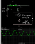
This concept may be useful for amplifying a thermocouple. A transistor in common base operation has a low input impedance, and high gain.

common base NPN amplifies thermocouple 100mV.png
By installing a series diode you can obtain output that goes down to 0V, if you decide that is essential.

- - - Updated - - -

I drew a generic stand-in for a thermocouple. It produces a voltage from 0 to .1V.
 
Hi,

I doubt that a single transistor solution could give a suitable amplifier for thermocouple signals.
The voltage of a thermocouple is about 0.04mV/°C
Wheras the Vbe drifts with about -2.1mV/°C
This is about 50 times of the thermocouple signal.
It needs at least a second bjt to compensate for the Vbe drift (thermally coupled to the other bjt)...

******
As asdf44 points out, one needs a "low offset drift Opamp". Whi,e initial offset can easily be cancelled out, any "drift" will cause errors.
Mind to thermally couple the LM35 to the cold junction point (X1). Also mind to use K-type extension wires, if necessary.

Klaus
 
I changed R23,C18,C20,R25,C26 and the result became a little bit better.
While thermocouple input shorted to GND and after installing the AVR ,the ADC0 voltage became 45mv.
I tried many times ,but I can't remove this 45 mv ,finally I readjust the offset potentiometer(R1) to make ADC0 equal zero .
Does my method good or not ?
My project is for measuring furnace temperature more than 400 degree celsius,
Furnace cabinet has closed muffle which has thermocouple and the circuit will be in the same cabinet. does it need to add cold junction point sensor (LM35)?
Will the cabinet temperature affect the measurement result?
View attachment 123.png
 

Hi,

It sounds like the AVR code is not correct.
Did you check your cide according my recommendations of post#2.
What's your sampling rate. (You need to know it)
--> Show your code.

does it need to add cold junction point sensor (LM35)?
Read post#5, read thermocouple measurement theory, do a forum search...

Klaus
 
Status
Not open for further replies.

Part and Inventory Search

Welcome to EDABoard.com

Sponsor

Back
Top