Continue to Site

Welcome to EDAboard.com

Welcome to our site! EDAboard.com is an international Electronics Discussion Forum focused on EDA software, circuits, schematics, books, theory, papers, asic, pld, 8051, DSP, Network, RF, Analog Design, PCB, Service Manuals... and a whole lot more! To participate you need to register. Registration is free. Click here to register now.

Create Block in innovus to use on other designs

Status
Not open for further replies.

rmachado

Member level 2
Joined
Apr 13, 2018
Messages
45
Helped
0
Reputation
0
Reaction score
1
Trophy points
6
Activity points
668
Hello,

I would like to know if there is a way to create a user defined cell composed by other cells (from a foundry library) using innovus.

The idea is basically the following: I have a block (composed for example by an AND cell and a Flip-Flop, from the libraries given by the foundry, where the output of the AND is connected to the input D of the Flip-Flop) that i want to use many times on other design. How can I add this block to my library files so I can instantiate it the verilog

thanks in advance
 

Yes, it's called a macro. Innovus will generate a LEF file for you that can be reused and instantiated later. Do not use this to create 'fake' standard cells, that will be a nightmare to manage.
 

Do you know how can I do that? I know how to do the floorplan, placea and route and then export the GDS, but after that how do i create the macro and where is the LEF file generated?
 

Hello again everyone,

So this tread is almost dead which made me realize that probably I had not explain myself correctly, and therefore nobody was able to help me out.
I will try to better explain myself with a clear example and we clear points on what I want to do.

So I have a design of a 16-bit counter. I synthesized it using Synopsys design compiler and then I imported the netlist into Cadence innovus. I placed, did CTS, routed, added fillers and run the verification tests regarding geometry, connection and antenna effect. Everything is good so I proceed to extract the RC parasitic, and I export the SDC and the Netlist from the design.

Now I want to use this 16-bit counter in another design. To do so I need to pass to Synopsys design compiler a db file with my counter right?

So the question is, what do I need to do to generated this db file from the innovus P&R design? Is it possible or do I need another software tool to do it?

Thanks in advanced,

Rui
 

Generally speaking, you don't want to do that. We make use of macros for analog/memory/special hardware, not for standard cell based modules.

The way to go would be to export a LEF file, a verilog file, and a .db/.lib file. The first two are easy, tools can generate both for you. The third one requires a proper characterization of your block for several input scenarios and loads. It is far from trivial. If you really really want to do it, I suggest looking into SiliconSmart or Liberate. It can generate .lib and .db files.
 

Thanks for the time to answer me @ThisIsNotSam.
What you said was according to what I was thinking. I went through the Innovus documentation again and probably what I need is to divide my design into partitions. Instead of a flat design I can implement my design in an hierarchical way and then, after synthesis, address the P&R of some specific modules separately from the rest of the design.
I am currently trying this out, but the innovus documentation is not the best thing ever so I am experimenting a little bit the process of creating partitions.
I am getting a warning when trying to specify some partitions saying that:
"The partition cannot be created without specifying a legal constraint on the partition module. specify a Guide, Region, or Fence constraint on the partittion module and then define the partition"
Any idea on how to solve this?
 

Partitions would be the way to go, yes. You can only create a partition on a module that has been 'turned' into a guide/region/fence. take a look at the command createFence for instance.

the flow goes:
- createFence myModule my_x my_y my_orientation
- definePartition -hinst myModule -[a bunch of routing/layer options]
- assignPtnPin
- partition
 

Ok, thanks, I will give it a try tomorrow at work.
Just another questions. Why do I have to do the procedure you mention to some modules while other can be automatically partitioned without the for creating a guide/fence/region manually?

Can you tell me if the flow I am following is correct?

1- Open innovus with the hierarchical design
2- load the design and define partitions
3- do place and trial route
4- commit the partitions
5- close innovus
6- go to the partition directory and open innovus
7- load the .v file of the partition and do the normal place & route procedures (including CTS)
8- generate the sdf, spef, def, v, and gdsII files (How do I do to generate the abstracs? do I need to create a OA library?)
9- close innnovus and return to the hierarchical design directory
10- open innovus and restore the hierarchical design to its previous point (after committing the partitions)
11- load the partitions so that the changes on the partitions can be applied
12- continue the process of place & route as usual
 

Are you dragging and dropping modules into the core area? That way they become ok for partitioning even without createGuide/Fence/Region.

Step 3 is optional, but it helps for pin assignment.

Step 7 is automated, innovus will save a tcl script in each partition folder. just load that, it will load all the necessary files for that partition.
Step 8 is not needed. Just do saveDesign, innovus will handle it all for you.
Step 10 should use assembleDesign command, no need to load any design. just start innovus with no argument, and issue the assemble command.
Step 12 should be more about analysis of the outcome rather than implementation. The entire goal was not to run any placement or routing at chip level, that's why you want partitions. You might want to do some OPT at chip level, however.
 

I am not dragging and dropping modules. I start innovus after getting the netlist from the design compiler and load the design along with the lef libraries and timing constraints.
Then I went to the partition menu and selected specify partition. After specifying only one of my modules I did ok.
Innovus automatically created me the partition I set and 4 other partitions from 4 other modules that I had in the design. I had 5 more modules but it did not created a partition automatically for them and when I tried to create them manually i got the error mentioned in the previous post. As these modules are not critical I did not bother and let the tool place the cellsas it desires. But i would like to know the reason behind some modules becoming partitions automatically and others not.

What I was trying to said in step 12 is related with this. as some modules are not part of any partition, I have to do the place and route of them after having the partitions ready.
 

If some modules don't become partitions, by definition they are part of the top partition. You should still perform place/cts/route for that one top partition too.
 

Can I do it in the main design or should I do it on the directory it creates for the top partition?
I will try all of your suggestions tomorrow.
Thank you again
 

you should use the top partition directory, it makes assembling easier later
 

ok this is gonna be a long post.

I decide to do the process all over again this morning to make sure I was understanding everything.
I open innovus and load my design files along with constraints, lefs, etc.
Then I issue the flooPlan command to set the area I need for the ASIC.
I then proceed to specify the partition. One thing I noticed this time. I went to the partition menu and select specify partition. I fill the instance name with the name of the module I wanted as a partition and then click ok.
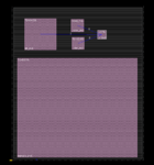
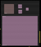
I noticed that the console gave me the error I mentioned on the previous posts but it still create the partion on the floorplan view (see following image)

patitions.PNG

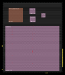
I reshape the partitions and drag them into the core area to get the result that is visible on the next image

patitionsReshaped.PNG

After this I do power planning (add power rings, stripes and special route)
Then I go again to the partition menu and specify my partitions and this time no error is issued by the console (I can not understand this at all)

then, as I am following the "Partitioning the Design" chapter of the innovus user guide i do the placement using placeDesign command.
The cells from each partition are placed inside the predefined area as expected.
Another thing I noticed was that the partitioned manually specified by me changed color. What does that mean? (image below)

patitionsColor.PNG

I proceed with the steps given in the user guide and perform trial route
so far so good...
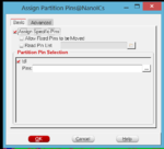
then I go and assign the partition pins using the partition menu and selecting assign pin... option (image below)

assignPins.PNG

I select all the pins of my module and click ok.

the console says that the operation concluded with success but I can not see any change on the design
then I run trial route again with the -honorPin option.
then the user guide says to validate the pin assignment results. What does that mean? I use the check pin result operation under the partition menu
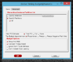
the next step in the user guide is to budget the timing for the block. I used the derive timing budget option on the partition menu (image below)

timeBudget.PNG

then I partion the design using the partion command which commits my partition (image below)

commitedpartition.PNG

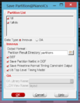
finally i save the partition using the file->save->partition menu (image below) (I went for the innovus data type, should I select OA?)

savePartition.PNG

no errors on the console and the directory with the partition was created.
I close innovus and change to the partition directory and run innovus from there.
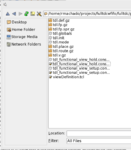
Here is the view of the files presented in the directory. the only tcl script there is the viewDefinition.

directoryView.PNG

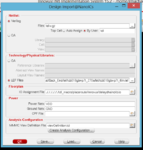
I run innovus and then do import design and chose the tdl.v.gz presented on the directory of the partition and pass the lef file and the mmmc constraints file. (I dont know of another way to do it since i dont see the tcl script you mentioned)

importDesign.PNG

I then proceed to change the size of my partion, specify the place in which I want the pins to be and do place, CTS and route operations. (I dont do power planning here because I am assuming that the top module is the one responsible for handling that right?)
After finishing in the partion i do:
saveDesign patitionName_ready.enc

and exit innovus
I go to the top partion directory this time and run innovus and try the assembleDesign command you sugested but i got an error saying that an unknow issue happen and that the problem can not be identified without further investigation (IMPTCM-83).
So I went to my main directory and run innovus and restore the design to the point were I was when I defined the partion. I try to load my partition using the File->load->partition menu.
I successfully load my partition with the pins the the right place, but I noticed that some of them are out of the boundaries of my partition. I guess I have to define very well the shape I want to the partion because I will not be able to change it later.
The place used will also be the one defined in the partion because even if you do place in the top module, it will only place the cells not belongging to a module right?

sory for the long post
 

First I suggest you stop using the graphical interface as it is known to be buggy, always has been. Script your flow.

You didn't use the createFence command I mentioned. That is probably breaking everything downstream.
 

I found out why innovus was issuing an error when i tried to define my partition. It seams that you need to put the partition inside the core are before trying to specify the partition.

Ok I repeated the process using only the command line and my scripts but the final result was the same.
Here are the the set of commands that I used:
1. Innovus
2. tsmcDBSetup (its a script that I have the configures innovus for the tsmc technology and automatically loads my netlist, constraints, rc corners and views)
3. Then I drag and drop my partition into the core area (this is the only thing I do using the graphical interface)
4. Then I run the following commands:
5. definePartition -hinst myPartitionName
6. placeDesign
7. trialRoute -highEffort
8. assignPtnPin myPartitionName
9. trialRout -honorPin
10. checkPinAssignment (to validate the pin assignment step)
11. deriveTimeBudget -ptn myPartitionName
12. partition (this command commits the partititon)
13. savePartition myPartitionName (this command creates a directory with exactly the same content as the one showed by me in the previous post)

After this I close innovus and go to the partition directory and run innovus. Then I do the the place and route using a script to iterate through all the phases from floorplan to place, CTS, route, and add fillers (basically a do the P&R normally as if this was just a regular design). Before exiting innovus I run the command:
1. saveDesign -def myPartitionName.enc

Then I go to the top partition directory and run innovus.
Again I load the design using my script (the same that I used to load the partition, the only change is the netlist that is not the same)
I save de design using the command: saveDesign -def myTopPartitionName.enc
Then I run the command:
1. assembleDesign -topDir myTopPartitionDir -blockDir myPartitionDir

this command adds the partition to the design but its size and shape has nothing related to the one I implemented so I am guessing something i wrong in the process.
 

the top partition part is wrong, you shouldn't be loading anything. just treat it as a leaf partition, let innovus load the files that it needs. run your place/route/cts/whatver flow for it and save it with saveDesign

Then start a new innovus session. don't load anything. just run the assembleDesign command.
 

I did as you said. I treat the top partition as a regular partition.
I did the place and route flow that I have in the top partition and as expected the cell from the other partition were not considered by innovus.
Then I start another innovus session and execute the following command:

assembleDesign -topDir myTopPartitionDir -blockDir myPartitionDir

It loads the top design and says that my partition was assembled, but I don't see it anywhere). Here are the console messages regarding the assemble command:

assembleResult.PNG
 

The command is correct, something else must be missing.
 

Thank you for your time.
I can not figure out what I am doing wrong here. I follow the guide they have on the user guide manual (although some steps are poorly described and probably I am doing some mistake in one of these steps).

I will have a training in September regarding Cadence tools, guess I will have to wait until there to clarify my doubts.
After the training I can share what was missing and a step by step flow of using partitions in this tread for future reference if someone has a problem similar to mine.

In the meantime, if someone knows of a tutorial or guide about using partitions in innovus please share it with me so I can learn more about it.
 

Status
Not open for further replies.

Part and Inventory Search

Welcome to EDABoard.com

Sponsor

Back
Top