Continue to Site

Welcome to EDAboard.com

Welcome to our site! EDAboard.com is an international Electronics Discussion Forum focused on EDA software, circuits, schematics, books, theory, papers, asic, pld, 8051, DSP, Network, RF, Analog Design, PCB, Service Manuals... and a whole lot more! To participate you need to register. Registration is free. Click here to register now.

Spice model "Lamp button"

Status
Not open for further replies.

eremabergen

Newbie level 1
Joined
Jul 1, 2018
Messages
1
Helped
0
Reputation
0
Reaction score
0
Trophy points
1
Activity points
14
Эл. схемка.jpg

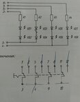
Hello! There is such a scheme, or rather 2, it's a lamp button. How to make SPICE model on it? Use standard switch models from the library? Simply, in general for zeros in this area, I looked at the manuals and everywhere I described only the syntax of the simulation and the parameters, and how to put them and for which devices are not specifically shown. If there are textbooks and training programs on modeling spice, pspice share please.
 

A spice switch model treats it as a four terminal device , where as a switch in practice is two terminal device.
You connect the switch between the two main terminals and control it by user defined voltage control.
This voltage is for simulating when switch is closed or opened manually.

see the following if you are using pspice :

https://www.uta.edu/ee/hw/pspice/pspice10.htm
 

It's not clear which properties of the "lamp button" you want to model. Who's operating it and when?

If you want to model a time programmed switch, you need e.g. a voltage controlled switch and a controlling source. Some SPICE variants, e.g. PSpice have "on" and "off" switch symbols for your convenience, you can make a respective subcircuit yourself if your SPICE doesn't have the simple time controlled switches.
 

Status
Not open for further replies.

Part and Inventory Search

Welcome to EDABoard.com

Sponsor

Back
Top