Continue to Site

Welcome to EDAboard.com

Welcome to our site! EDAboard.com is an international Electronics Discussion Forum focused on EDA software, circuits, schematics, books, theory, papers, asic, pld, 8051, DSP, Network, RF, Analog Design, PCB, Service Manuals... and a whole lot more! To participate you need to register. Registration is free. Click here to register now.

AC sinewave sampling circuit

Status
Not open for further replies.

UroBoros

Advanced Member level 2
Joined
May 5, 2004
Messages
642
Helped
19
Reputation
38
Reaction score
8
Trophy points
1,298
Location
Cochin - India
Activity points
6,463
I am trying to sample s sine wave for zero crossing detection as well as other measurements. But I would like to avoid the method of directly connection to AC mains using dropping resistor and then sampling.
My MCU works from a step down transformer power supply. So 0-12 v Step down isolated sine wave is available in my board. I prefer to use this voltage. correct me if I am wrong. somehow I feel the resistor network connected to live AC seems risky for me.
May I know how I can bring this step down transformer AC output wave to 0 to 5 volt range so that MCU ADC can see the waveform as centered in 2.5V.

Thank you
 

Hi,

There are a lot of discussions about AC mains voktage measurement.
I've posted schematics. Do a forum search.

Why do you think the resistor method is risky?
Use suitable devices.
It is done many times. I do this with even with 2500V AC.

You say zero cross....
The problem with transformers is, that they introduce phase shift.
I don't like the idea to use an ADC as ZCD...because a comparator is way more precise in time.

Klaus
 
Thanks for the response.
First of all, my aversion towards resistor mechanism was mainly derived from posts like this. I think I will get rid of that. mainly phase shift is not something I should prefer to introduce. So I think I will move over to resistor network
Zero cross is my immediate requirement, i mentioned ADC method with a future plan to derive Precise voltage reading from same hardware.
I was not able to find the schematics you have posted. if possible please share details/links about best option/circuit in your opinion for my case.
Thanks
 

Hi,

https://www.edaboard.com/showthread...nt-using-pic&p=1520931&viewfull=1#post1520931

You need to know about safety regulations you need to choose correct resistor values.
If you are not experienced in working with dangerous high voltage and how to design a PCB for this, then don't go on with this design.

Usually I use double safety: choose two high side resistors in series. Each one is rated for much higher voltage (not only the expected AC voltage). Like HV isolated 0207 or larger wired resistors (like Vishay VR25). Calculate that the current is limited to a safe value, even if one resistor accidentally is short circuit.

Mind: a phase tester also works with current limiting resistors .... and the whole measurement current runs through your body.

Klaus
 
how I can bring this step down transformer AC output wave to 0 to 5 volt range so that MCU ADC can see the waveform as centered in 2.5V.

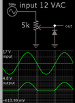
A simple way is to reduce amplitude by a potentiometer, then a diode shunts the negative portion.

attenuate 12VAC via pot then 0-5V diode removes neg portion.png

You can also try putting the diode in series to pass only the positive portion. It subtracts 0.6V. Choose whichever works for you.

- - - Updated - - -

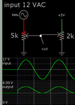
To do what you requested, two potentiometers can be used. One attenuates the AC, another pot applies a voltage between 0 and +5V.

lift 12VAC to 0-5V using two pots.png

- - - Updated - - -

The output is AC riding a 2.5 VDC component. However it may not be easy to accommodate all high and low values of house voltage.
 
Thanks for the link.
I can work with Voltages of this level and initially I will be working with isolation transformers of 1:1 at 230V side.
btw I found some circuits with microchip using op-amps to do this.
Screenshot 2018-06-23 12.43.10.png
Except the presence of more filters is there any advantages worth the extra components count in your opinion?
Also the Simulation circuit not shows two lines of AC. should we pay attention to the L and N lines of AC 230V supply in this circuit?
Thanks

- - - Updated - - -

The output is AC riding a 2.5 VDC component. However it may not be easy to accommodate all high and low values of house voltage.

Even though the waveform doesn't seems to be equally placed on the sides of 2.5 volt, it seems this can also do the job provided we are ready to accommodate the phase shift from transormer!
How worse will be the impact of this phase shift in an application like a Battery charger?
Thank you
 

Hi,

The benefits of the Microchip solution against my solution:
* differential input
* less output impedance
* not urgently needed to connect microcontroller_GND with Neutral/Earth_GND (but I recommend this. But this on the other hand negates the benefit of differential input)

The drawbacks:
* if not connected to Neutral/earth: touching the circuit will cause noticable high measurement current
* you need a 5V and a 3.3V supply
* you need a stable 2.5V reference
* drifts in 2.5V reference as well as drift in ADC_reference cause DC offset
* opamp causes offset drift
* higher part count and cost
* I personally don't like SMD devices in safety circuits, because solder and flux residuals between PCB and chip resistor may cause invisible paths for leakage currents. Difficult to clean properly.

Klaus
 

Status
Not open for further replies.

Similar threads

Part and Inventory Search

Welcome to EDABoard.com

Sponsor

Back
Top