Continue to Site

Welcome to EDAboard.com

Welcome to our site! EDAboard.com is an international Electronics Discussion Forum focused on EDA software, circuits, schematics, books, theory, papers, asic, pld, 8051, DSP, Network, RF, Analog Design, PCB, Service Manuals... and a whole lot more! To participate you need to register. Registration is free. Click here to register now.

Whats wrong with my full wave bridge rectifier?

Status
Not open for further replies.

rabinsakha

Newbie level 4
Joined
Dec 16, 2009
Messages
7
Helped
0
Reputation
0
Reaction score
0
Trophy points
1,281
Activity points
1,323
Whats wrong with my full wave bridge rectifier

whats wrong with my full wave bridge rectifier?
 

Attachments

  • Capturemail.PNG
    Capturemail.PNG
    40.3 KB · Views: 174

Re: Whats wrong with my full wave bridge rectifier

No DC input.
Connect GND to left of bridge.
 

Re: Whats wrong with my full wave bridge rectifier

Thank you for the reply. I am getting output of the rectifier by vout2-vout1 as shown in the equation. The thing is i am getting very low efficiency. Even impedance matching is not helping me to get higher efficiency.
 

Re: Whats wrong with my full wave bridge rectifier

It's not obvious what your meter is measuring. Volts or Amperes?

I believe you should connect a voltmeter across the capacitor and resistor.
 

Re: Whats wrong with my full wave bridge rectifier

It's not obvious what your meter is measuring. Volts or Amperes?
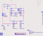
I_PROBE device name suggests the latter.

The thing is i am getting very low efficiency. Even impedance matching is not helping me to get higher efficiency.
How did you try impedance matching? Presently we see a large series inductor L1 that's probably dropping most of the input voltage.
 
Re: Whats wrong with my full wave bridge rectifier

I am getting output of the rectifier by vout2-vout1 as shown in the equation.
The thing is i am getting very low efficiency.
I think it is natural.
Your load is floating, on the other hand, a drive is single-ended.
 

Re: Whats wrong with my full wave bridge rectifier

Thank you for the reply.
I tried impedance matching using smith chart utility. If L1 is dropping most of the voltage, should i avoid using inductor in matching. What are the ways i should try to increase efficiency?
 

Re: Whats wrong with my full wave bridge rectifier

Thankyou for the reply.

What can i try to increase the efficiency of this bridge rectifier?
 

Re: Whats wrong with my full wave bridge rectifier

Thank you for the reply. i tried impedance matching using smith chart utility. If L1 is dropping most of the voltage, should i avoid using inductor in matching. What are the ways i should try to increase efficiency?

- - - Updated - - -

Thank you for the reply,

i have removed the i probe and voltage measurement is done as vout= vout2-vout1 , from the pin voltages vout1 and vout2 as shown in the figure
 

Re: Whats wrong with my full wave bridge rectifier

i tried impedance matching using smith chart utility.
How did you determine the rectifier input impedance?
 

Re: Whats wrong with my full wave bridge rectifier

i used the ADS tool Zin to calculate the real and imaginary part of input impedence
 

Re: Whats wrong with my full wave bridge rectifier

How did you calculate the efficiency ?
Have you considered the Power factor ?
 

Re: Whats wrong with my full wave bridge rectifier

Insufficient information.

Please let us know the approx frequency and then also approx magnitude.

Calculate the reactance of the inductor and capacitor at the typical frequency.

I do not see anything wrong with the full wave bridge rectifier. Once you get an idea of the expected value then we can compare with the observed value.

Is the diode rated for high frequency operation?
 

Status
Not open for further replies.

Part and Inventory Search

Welcome to EDABoard.com

Sponsor

Back
Top