Continue to Site

Welcome to EDAboard.com

Welcome to our site! EDAboard.com is an international Electronics Discussion Forum focused on EDA software, circuits, schematics, books, theory, papers, asic, pld, 8051, DSP, Network, RF, Analog Design, PCB, Service Manuals... and a whole lot more! To participate you need to register. Registration is free. Click here to register now.

UART condition in PIC18F65K40

Status
Not open for further replies.

vilfred

Member level 1
Joined
Mar 21, 2018
Messages
37
Helped
0
Reputation
0
Reaction score
0
Trophy points
6
Activity points
368
Hi...
May i know the conditions for asynchronous Uart transmission in PIC18F65K40. I'm using PORTC 0th pin and 1st pin as TX, RX, but those pins does not share with analog/digital pins, it only shares with timer pins, So how to initiate those pins for UART?
 

Hi,

I recommend to read the datasheet. The Microcontroller has 5 built in USARTs.
The datasheet tells you which pins to use and how to use the interface. Usually all you need to know.

But the manufacturer gives additional assitance by
* the MPLAB code generator
* a lot of application notes on how to use the USART
* giving code examples

* and a lot more documents, turorials, code examples and viedos at the internet.

If you just refer to the PPS feature, there is a good description with example in the datsheet, too.
(you mention "analog"... this has nothing to do with USART)
According Table 17-1 only USART1 and USART4 is available for PORTC

Klaus
 

Thanks for your reply. I'm using EUSART4 i.e. RC0,RC1 to interface my RS422 driver.I assigned the pins for uart operation by writing


RX4PPS = 0x11; //EUSART4 Receive
TX4PPS = 0x10; //EUSART4 Transmit

is that enough to make my pins for uart transmission and reception
 

In theory it should be as the EUART should set everything else for you.
However I always recommend that you set the TRIS registers appropriately.
In this case the pins you are using do not have analog functionality but the general rule is to always set the pins to 'digital' mode. Leaving a pin in analog mode for an output (TRISxn=0) can work but trying to read a digital input from a pin set to analog will always result in a '0' being read. Analog/Digital is one of the most common sources of problems for beginners with the PIC MCUs.
Susan
 

Thank you susan, I'm struggling with this UART in pic18f65k40. This MCU's PORTC doesnot have analog function, i also tried by setting as

TRISC = 0b00000010; // RC0 is Transmitter, RC1 is Receiver

Provided in datasheet that RC1 pin shares RX4 and DT4, according to me for synchronous mode only RC1 should be chosen as RX4/DT4, otherwise it act as receiver pin, Am i correct?

- - - Updated - - -

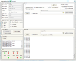
After setting 'TRISC = 0x00' , i got a garbage value, please look at the attached image. But if i set RC0 - TX as output and RC1 - RX as input like

TRISC = 0b00000010;

I not even received this garbage value uart.PNG
 
Last edited:

Hi,

I'm not familiar with PICs. But if I understand the example right...
Datasheet says:
The peripheral input is selected with the peripheral xxxPPS register, and the peripheral output is selected
with the PORT RxyPPS register . For example, to select PORTC<7> as the EUSART RX input, set
RXxPPS to 0x17 as shown in the input table, and to select PORTC<6> as the EUSART TX output set
RC6PPS to 0x0C as shown in the output table.
Thus I expect you set output pin of PC0 to USART4Tx with this:

RC0PPS = 0x12

Klaus
 

Sir,
Thanks for your reply, i tried this but still there is no output,
RX4PPS = 0x11; //xxxPPS register
RC0PPS = 0x12; // RxyPPS register
MCU doesnot transmit the received value or the value stored in TXREG. If program is wrong whether it produces output in proteus
 

Hi,

I assume you additionally need to setup TRISC and USART4.

If you want us to verify it you should show your complete code and also your complete schematic.. with complete wiring to the PC.

Klaus
 

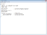
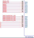
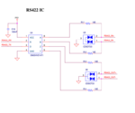
I'm doing program in mikroc, there present header files for uart. Hereby i attached a code which is copied from the example program given by mikroc, this is what i tried in my circuit. Also i attached schematic of my Transceiver and uart part of microcontroller.

program1.PNG
Capture11.PNG
1.PNG
 

Hi:

* In the text you write: "RC0 - TX as output and RC1 - RX as input like" but your schematic shows it the other way round.
* According SN65HVD1471 datasheet: "Z = inverting output; Y = non iverting output", but your schematic shows it the other way round.

Klaus
 

Thanks again for your reply,
According to schematic RC0 is connected with RS422_RX i.e. RC0 is a TX pin which is connected to RX pin of RS422. And yes Z is a inverting output and Y is a non-inverting output, in schematic i mentioned wrongly(it just a words written there wrongly), but in terms of connections i did correctly. I used RS232 to RS422 convertor which is connected with USB to DB9 cable, and the connections are below,

VCC - +5V
GND - GND
TX+ - A
TX- - B
RX+ - Y
RX- - Z

Is it a correct connection? because during driver testing, i've shorted R and D pin and connected A,B,Y,Z as above i got a result i.e. whatever i typed in terminal window the driver gives it back .
 

Hi,

just read datasheets.

* SN65HVD1471 pin "R" is clearly declared as output
* you connected this to your signal "RS422_RX"
* you connected the same signal to RC0
* you declared RC0 to be an output.

Thus you short output with output.
It´s not unlikely that you damaged a device.

Klaus
 

Hi..
Thanks klausST, Finally that is the mistake in my schematic. All the RS422/RS485 Transceivers are connected in the same manner, so according to my transceiver , SN65HVD1471 the R pin should be connected to a digital input (Rx) of a micro-controller to read the data received by the transceiver (on pins A and B), and the D pin should be connected to a digital output (Tx) of a micro-controller to drive the transceiver output (pins Y and Z). And connections from RS232 - RS422 convertor to differential pair remains same as mentioned above.
Then, termination resistors should be used between each differential pair (A to B and Y to Z) at each cable end (first and last device on the bus). The value of these resistors should match the characteristic impedance of the cable being used. This value for most twisted pair cables is 120-Ohm.
 

Hi,

This all sounds good.

The only thing that worries me is "RS232" .... because there is no RS232 in your schematic...

Klaus
 

Status
Not open for further replies.

Similar threads

Part and Inventory Search

Welcome to EDABoard.com

Sponsor

Back
Top