Continue to Site

Welcome to EDAboard.com

Welcome to our site! EDAboard.com is an international Electronics Discussion Forum focused on EDA software, circuits, schematics, books, theory, papers, asic, pld, 8051, DSP, Network, RF, Analog Design, PCB, Service Manuals... and a whole lot more! To participate you need to register. Registration is free. Click here to register now.

Measuring Leakage Current for Differential Drive CMOS Rectifer

Status
Not open for further replies.

Khan2813

Newbie level 2
Joined
May 17, 2018
Messages
2
Helped
0
Reputation
0
Reaction score
0
Trophy points
1
Activity points
22
Hi

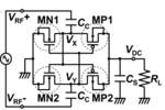
I am designing single stage Differential Drive CMOS cross coupled bridge Rectifer for Passive RFID using 65nm technology at 5.8GHz in Cadence. Now i wanted to observe the effect of reverse leakage current on my rectifier performance, how can i do that since i do not have any supply. Which simulation should i run?
Attached file is the schematic of rectifier.
 

Attachments

  • 2.PNG
    2.PNG
    29.6 KB · Views: 113

Now i wanted to observe the effect of reverse leakage current on my rectifier performance,
how can i do that since i do not have any supply.
I can not understand what you want to mean at all.

Which simulation should i run?
HB-PSS or Shooting-Newton-PSS Analysis, if you want to evaluate reverese current leakage during one RF period.

Use transient analysis with initial condition at load capacitor, if you want to evaluate charge hold characteristics for zero RF input.
 
Last edited:

Status
Not open for further replies.

Similar threads

Part and Inventory Search

Welcome to EDABoard.com

Sponsor

Back
Top