Jadeit
Member level 5
I propose a 4th order filter for smoothing the voltage for the RF power transistor amplifier.
See on picture
Q1 and L1 is RF power amplifier on 10MHz
C10,C5,C4,C3 is voltage source for this amplifier and last stage of 4th of LC filter too.
L5,L2 and all C is 4th filter for smoothing voltage between the V1 and Q1.
L2 I choice WIDE BAND CHOKE 3turn in ferrite tube 1000Ohm on 25MHz
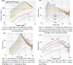
The question is what to use as L5? The requirement is min 10k Ohm on 25MHz.
Is good idea use as L5 any as power SMD 1207 ?
Of course I am interested in the opinion of C in the filter.

