Continue to Site

Welcome to EDAboard.com

Welcome to our site! EDAboard.com is an international Electronics Discussion Forum focused on EDA software, circuits, schematics, books, theory, papers, asic, pld, 8051, DSP, Network, RF, Analog Design, PCB, Service Manuals... and a whole lot more! To participate you need to register. Registration is free. Click here to register now.

DC Current pulse sensing

Status
Not open for further replies.

knikhil271083

Member level 2
Joined
Jul 17, 2012
Messages
45
Helped
1
Reputation
2
Reaction score
1
Trophy points
1,288
Location
India
Activity points
1,676
Dear Experts,
I want to design a circuit that senses change in current flowing through a variable load. The current is DC and the load draws anywhere between 90mA to 300mA nominal. During a fault condition, the load the load current dips (reduces) briefly for around 200us by 20mA and then goes back to 300mA. This means that, for let's say 300mA load current, the current goes to 280mA for around 200us and returns back to 300mA. The common voltage is 48VDC.
I am planning to use a current sense amplifier like TI's INA301 or similar to sense the current but I don't want to use an ADC to detect the current dip. I want to use a comparator so that I can just get a '1' or '0' when the current dips 20mA.

Any ideas or hints of how I can achieve this?

Thanks in advance for the help.

Regards
Nikhil
 

Hi,

You may use a current sense amplifer. But then use a high pass filter. (If you are working with single supply only. then use a voltage divider to add a bias voltage. )
This filters away the DC and just shows the fluctuations.

Now use a comparator and set the threshold slightly below the bias voltage. (the difference should equal to 10..15mA)
(4 resistors and 2 capacitors)

Klaus
 
Hi,

Maybe consider things like common mode range of comparator, as wise a choice of overdrive voltage as possible of input signal, will it chatter a lot and will it be more or less accurate as needed if hysterisis needs to be added to remove endless chatters - if it's counting the 280mA events, then that chatter is a help I guess.

I'd also be seeing what way I want to - and more importantly can - use the comparator inputs and not get caught out with stuff like: trigger voltage set within common mode range = High Z output and trigger voltage level may get outside of common mode range and reverse the planned functionality = High Z output (not Output Low). I take the coward's/lazy designer's way out, I design to keep the inputs within common mode range.


I'd probably also want to think about what's upstream of the comparator and definitely place some logic gate or other or a flip flop between them to get guaranteed switching as desired, not crummy comparator output low being 2V off ground..! Need to consider weight of pull up and ideally much larger weight of load compared to pull up resistor and if the circle can fit that square.

Also, obviously, I think I'd choose a ref and trigger as far in scale as possible: 20mV is very doable but very dodgy when you could have a whole 200mV for the overdrive voltage and a clear line/distance from on and off levels.

Bitter experience: design in to the comparator switching point the guesstimate current monitor's input offset and other noise that will appear at the output/comparator input, it might add up to quite a few mA and you probably don't want that kind of heartbreaking inaccuracy. I have a simple Sigma-Delta ADC ammeter driven by a good current shunt monitor and at 0mA apparently there are 5mA to 7mA of noise forever - it's mostly/mainly from the current shunt monitor - I hadn't known to plan for it.
 
Last edited:
Thanks KlausST & d123,
I will simulate a circuit and share the result with you all.

Nikhil
 

Hi,
I have simulated the circuit using LTSpice. See attachment. I have used LT6100 current sense amplifier and OP07 for comparator. Though these are not the final components, I have used what are readily available in LTSpice.
I am getting lag at the output wr.t the current pulse.
kindly have a look. Any suggestions for design improvements are always welcome.

Nikhil Current Sensing.JPGCurrent Sensing_1.JPG
 

Hi,

OP07 is an Opamp, not a comparator.
--> I recommend to use a comparator.

Opamps are not made for
* input difference voltage about zero
* output voltage not touching the power supply rails.
The opposite is is true for comparators.

Many Opamp suffer from overdriven inputs and outputs as soon as the output touches the supply rail. Resulting in large delay to come back to regulated state.

There's a good reason why they design Opamps and comparators differently. Sadly both use the same schematic symbol.

Klaus
 
Hi knikhil271083,

I agree with Klaus.

Try using an op amp for a comparator and basically get disappointing results unless the requirements are fairly loose. "Sadly both use the same schematic symbol" never better said - Beginners error in my case was thinking SMPS control loops are two op amps but they are an op amp and a comparator... Op amp based window comparators are even worse: a hassle to level shift the neither high nor low output to anything useful, comparators do that part by nature.
 
Dear Experts,
These are useful insights. I will implement these suggestions and come back.

Nikhil
 

Hi Experts,
I have shortlisted the following parts for my design:
1. Current Sense Amplifier: LMP8601
2. Comparator: LM331

Basically, I will interface comparator's output to a micro-controller pin directly.
Any suggestions for other parts (which you have already used) is most welcome.

Nikhil
 

Hi,

There´s a mistake in the schematic of post#5:

I wrote:
Now use a comparator and set the threshold slightly below the bias voltage. (the difference should equal to 10..15mA)
But your threshold voltage is higher than V_Bias.

To reduce drifts:
You may use a three resistor string divider:
GND - [10k] - (V_TH) - [600 Ohms] - (V_bias) - [10k] - 5V
use additional 10k from V_bias to the capacitor (instead of your 2k)
Stabilize V_Th with a 10uF capacitor to GND.

Klaus
 

Hi Klaus,
Thanks for pointing this. I have made changes as per your suggestions.
Please see attached images of circuit and waveforms. Waveforms look much better now.

Nikhil


Current Sense_Modified.JPGCurrent Sense Waveforms_Modified.JPGCurrent Sense Waveforms_Modified.JPG
 

Hi,

I strongly recommend not to mis-use an Opamp. Don't be surprised if the real circuit doesn't behave like the simulation.

What happened to my 3 resistor string solution? See where V_bias is.
My solution for V_th and V_bias just needs 4 resistors instead of your 8 resistors.
--> lower part count but improved performance.

Klaus
 

Hi Klaus,
Sorry, but I think I did not understand the 3 resistor string solution. Can you share a circuit of how to do it?

Nikhil
 

Hi,

GND - [10k] - (V_TH) - [600 Ohms] - (V_bias) - [10k] - 5V
What is not clear?
Solder three resistors in a string: 10k, 600R, 10k.
Solder one end to 5V, the other end to GND
Use one leg of the 600R for V_th, the other end for V_bias.

Additionally:
Use a series 10k for V_bias to the capacitor
Use a capacitor to stabilize V_th

Klaus
 

Aaah...got it...so simple. Apologies for not understanding simple statement. Here is the circuit.

Current Sense_Modified_1.JPG
 

Hi,

I´d say R6 gives no benefit. Omit it.
Don´t forget to use a single bulk capacitor on +5V and additionally a ceramics capacitor for each IC.
Also use a bulk capacitor on +34V

Klaus
 
Hi Experts,
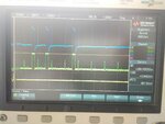
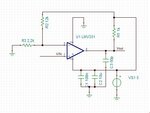
I have built the circuit using useful help from this post. I am getting the current pulses at output of current sense amplifier. As discussed previously, I am using a comparator LMV331 to determine whether the current pulse is present or not.
However, the output of the comparator is distorted. See the attached waveforms. The green waveform is current pulse and blue waveform is comparator output. I am using comparator in the configuration as per datasheet (screenshot attached). I have a 0.1uf & 10uF capacitor at supply pin of comparator. Pull-up at output is 5.1K.
Any clues on why this might be happening? What can be done to get a clean output.

Nikhil
IMG_20180630_102958467.jpgComparator.JPG
 

Hi,

I don't like the capacitor at the output.
If you want it to act as a filter, then add a series resistor.

But the waveform is not the problem of the circuit or the capacitor, it most probably is
* a not useful scope probe (use a calibrated 10:1 one), (this is my favourite)
* or a not suitable GND wiring (do you have a solid GND plane?)
* or the scope_GND connection is not suitable.

Klaus
 

Hi,
Actually, I still have not got the PCB done. I have done this hand soldering and wiring on a general purpose PCB.
I will check the scope probe calibration and get back.

Regards
Nikhil

- - - Updated - - -

Hi,
Actually, I still have not got the PCB done. I have done this hand soldering and wiring on a general purpose PCB.
I will check the scope probe calibration and get back.

Regards
Nikhil
 

Status
Not open for further replies.

Part and Inventory Search

Welcome to EDABoard.com

Sponsor

Back
Top