Continue to Site

Welcome to EDAboard.com

Welcome to our site! EDAboard.com is an international Electronics Discussion Forum focused on EDA software, circuits, schematics, books, theory, papers, asic, pld, 8051, DSP, Network, RF, Analog Design, PCB, Service Manuals... and a whole lot more! To participate you need to register. Registration is free. Click here to register now.

Common Mode Feedback

Status
Not open for further replies.

Majid_Vatan_Parast

Junior Member level 3
Joined
Oct 15, 2016
Messages
25
Helped
0
Reputation
0
Reaction score
0
Trophy points
1,281
Activity points
1,498
Hello
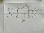
I want to design a capacitive common mode feedback , I have a circuit but it does not work .Can anyone tell me the problem of the circuit ?
Capture.PNG
 

Not until you have disclosed what your circuit looks like? The one in the picture is from a lecture. Are you replicating it properly in your schematics?
 

My circuit is exactly like that . My picture is shown in the picture .photo_2018-06-07_11-12-46.jpg
 

Attachments

  • photo_2018-06-07_10-57-53.jpg
    photo_2018-06-07_10-57-53.jpg
    114.2 KB · Views: 73
Last edited:

Ok... and all the voltage levels ? Vcm, Vb3 - how are they generated? And the clock phases are properly generated?

In which way doesn't it work?
 

For simplicity voltages are generated by DC voltage sources , clock phases are generated by a Non-Overlapping clock generator .Schematic of the circuit ,and voltage of output node are shown in the following pictures.1.PNG2.PNG
 

Please annotate the DC voltages and also annotate the graph and draw all nodes in the schematic. This is very hard to follow. How do you conclude that it does not work?
 

When I change the size of PMOS transistors at the top of the circuit , DC voltage of output nodes changes and CMFB can not tie them to desired voltage , that is why I think CMFB circuit does not work .
 

What is Vcm and Vb in your circuit?
 

Vcm is the desired DC voltage of output nodes . Vb is the voltage that must be applied to gate of tail transistor to generate desired tail current .
 

Yes, I know that. But what's the value of them?

- - - Updated - - -

How do you generate them?
 

Vcm=930mv , Vb=600mv .I use DC voltage sources to generate them.
 

(And the supply voltage is? Try annotate DC node voltages in the schematics and it's so much easier for us to see.)

Ok, even though it might not solve the issue yet, but generate the voltages with currents instead. For the PMOS use a current mirror with a known current to set the voltage. Do the same for the NMOS tail current source with a current that is twice the PMOS currents. That will give a first balance to the design.

Vcm = half the supply voltage?

- - - Updated - - -

Check also the operating region of the five transistors in the diff pair. Are input transistors on with 600 mV?
 

Voltage source is VDD=1.8 .Input transistors gate voltage is 0.8v. Vcm is a little bit more than VDD/2(Vcm=930mv).
3.PNG
 
Last edited:

Status
Not open for further replies.

Part and Inventory Search

Welcome to EDABoard.com

Sponsor

Back
Top