Continue to Site

Welcome to EDAboard.com

Welcome to our site! EDAboard.com is an international Electronics Discussion Forum focused on EDA software, circuits, schematics, books, theory, papers, asic, pld, 8051, DSP, Network, RF, Analog Design, PCB, Service Manuals... and a whole lot more! To participate you need to register. Registration is free. Click here to register now.

[SOLVED] Design precaution of 78xx and 79xx series regulators

Status
Not open for further replies.

Alan8947

Full Member level 4
Joined
Sep 21, 2016
Messages
215
Helped
9
Reputation
18
Reaction score
11
Trophy points
1,298
Activity points
3,746
Hi

I am looking into using these old regulators. My main concern is the maximum value of capacitor that can be used at the input and output. Datasheet of ON-Semi gave the minimum value. eg. 0.33uF at the input if the input trace is long. Suggest using like a 1uF at the output for stability purpose.

I understand I need to put 0.1uF ceremic bypass as close to the input and output as possible to give good bypass for stability. My question is whether it will present a problem if I use a lot more capacitance. eg, using 1000uF at the input to filter out all the ripple of the bridge rectifier after the transformer. I want to use like 1000uF at the output also( of cause with 0.1uF ceramic cap in parallel to take care of the RF).

Thanks
 

The capacitance at the input shouldn't be a problem; excessive capacitance at the output might cause excessive current to flow, but those devices have built in protection. But unless there's a good reason, why such a large output cap?
 

The capacitance at the input shouldn't be a problem; excessive capacitance at the output might cause excessive current to flow, but those devices have built in protection. But unless there's a good reason, why such a large output cap?

Thanks

So It's ok to have excessive caps at the input and output without worrying of oscillation.

For audio amp, the more capacitance on the rail the better. This is to power the preamp portion it's important to get rid of the 60/120Hz ripple.
 

Hi,

There is no input capacitor limit. Use what you want.
I don't recommend to use that big capacitors at the output. It gives no benefit.

It just causes long charging time and it causes a lot of reverse energy when powered down.

Klaus
 
  • Like
Reactions: burai

    burai

    Points: 2
    Helpful Answer Positive Rating
Hi,

There is no input capacitor limit. Use what you want.
I don't recommend to use that big capacitors at the output. It gives no benefit.

It just causes long charging time and it causes a lot of reverse energy when powered down.

Klaus

Thanks

I am planning to put a reverse diode from output to input so when the input discharged, it will drag the output down. It's a common way to protect the output from having higher voltage than the input.

I just want to have a lot of caps at the output to make sure the rails are really quiet.
 

You don't just arbitrarily throw large capacitances on there; do some engineering, i.e., develop a specification. As already said, you can have unlimited capacitance on the input; if you really like huge capacitance, put it there. Putting capacitors at the devices you're concerned about will also have a better effect on noise than a single enormous capacitor 6 inches away.
 

You don't just arbitrarily throw large capacitances on there; do some engineering, i.e., develop a specification. As already said, you can have unlimited capacitance on the input; if you really like huge capacitance, put it there. Putting capacitors at the devices you're concerned about will also have a better effect on noise than a single enormous capacitor 6 inches away.

I am designing audiophile power amps that measure under 0.004% THD across the audio frequency band, everything matters. Ground loops, ground bounce, wiring inductance and resistance.....Everything matters. I had to pay for $25 per pcs of the ultra fast bridge rectifier, or else even if I move the input coax, the THD change at 20KHz!!! I design the pcb as if it's RF circuit with ground and power planes!!! I use over 1.5F total of capacitors for filtering.
 

It's pretty much an established fact that nobody can detect the difference between .1% and .01% distortion and most people (and I'm including self-proclaimed audiophiles) can't even detect anything below 1%. But if you've got customers willing to pay a hefty premium to be able to brag about their .004% distortion amp, go for it. Of course, when they hook the amp up to their $13000 Bowers and Wilkins speakers, they're going to get 0.3% distortion.
 

It's pretty much an established fact that nobody can detect the difference between .1% and .01% distortion and most people (and I'm including self-proclaimed audiophiles) can't even detect anything below 1%. But if you've got customers willing to pay a hefty premium to be able to brag about their .004% distortion amp, go for it. Of course, when they hook the amp up to their $13000 Bowers and Wilkins speakers, they're going to get 0.3% distortion.

Big difference, this is not the thread on audiophile, I can tell you it's big difference. I have good amps like Nakamichi PA-7 stasis designed by Nelson Pass to compare. Big difference.
 

Hi,

I had to pay for $25 per pcs of the ultra fast bridge rectifier
Congratulations for the seller. He did a good job.

I use over 1.5F total of capacitors for filtering.
Nice, but not necessary.

everything matters.
Some time ago I also designed audio amplifiers, digital volume control, measurement tools...
I agree with you that when you go into details about "everything matters".
Some details are "philosophy" and can´t be measured.

Without knowing amplifier type and specifications (like maximum current) the value of 1.5F is meaningless.
Usually such big capacitors are used to suppress very low frequency fluctuations.
But on the other side these frequencies are not audible.
These capacitors usally are in power supplies. Power supply fluctuations should be suppressed by the PSRR of a class A or AB amplifier to a non measurable value.
But in class D the audio signal may be modulated with these fluctuations.

***
If you go into that deep with designing audio amplifiers... May I ask why you use the - not very audiophile - LM78xx voltage regulators?
There are better ones...in the meaning of: Low noise, faster response, higher current, push-pull....
You could even design your own.

Honestly, I´m convinced that a good regulator will result in less noise and more stable power supply than the huge capacitors.
On the other hand even a good regulator can´t replace cpacitors.

Klaus

- - - Updated - - -

Hi,

Big difference, this is not the thread on audiophile, I can tell you it's big difference. I have good amps like Nakamichi PA-7 stasis designed by Nelson Pass to compare. Big difference.

Did you try to recognize it in a double blind test?
I´ve seen a lot people they are convinced, but never seen one that could do that.

Klaus
 

There are people that into hifi audiophile amps here? That's good news. I did not see any section here. What section I should go to talk about power amps?

I find CMRR of normal amp is not necessary enough. When I ran FFT, I can still see the 60, 120 and 180 peaks be that they are low. It's the IM I am worry about mixing with low frequency.

I find not all speakers are critical with amps, I was actually surprised the very high end Wilson speakers are not that picky on amps. I have a JM Lab Spectral 913.1 which is the upper middle line of JM Lab, it is very picky on amp and speaker cable. I did casual blind test with a few people and they sure can tell the difference.

THD is not the whole story, actually is very miss leading. Manufacturers play game with THD, first they use linear resistor as load to test THD. Speakers are not linear particularly with crossover. I find another factor even more important is output impedance of the amp ( damping factor)......not with GNFB, but the open loop output impedance.

With my speaker, the amp and the speaker cable really matter. I build my own cables using 6+ pairs of 16 gauge twist together. I definitely can hear the sound open up.

I cannot speak for other speakers, I know Martin Logan is another one that is hard to drive.
 

I think you will find the expertise on Edaboard is mostly technical rather than subjective. We deal in theory and numbers, not "I definitely can hear the sound open up".

I'm not saying that to put you off, if there is a discernible difference in sound we would like to know the reason, whether THD or the more likely TID so we can consider it in future designs. Transient Intermodulation Distortion (TID) is a far more likely culprit than THD when a difference is seen under different loads and cables. It is the result of distortions caused at the load (rather than the amplifier) being fed back through the negative feedback paths.

Brian.
 

This is just my theory. THD creates harmonics ( of cause!!!), all the harmonics inter2mix together and form new frequencies like f1+/-f2, 2f1+/-f2, f1+/-2f.....etc.

If you just look at 2 tone, it's quite simple. BUT if you think of audio signal, it's a lot of different frequencies running at the same time. For an amp with distortion, all the IM literally form a noise floor Correlates with the audio signal. It's like a background to the original signal. With low distortion, the IM goes lower. Particular in my experience, my amps don't have much harmonics beyond 3rd or at worst 5th harmonics. So the floor is much cleaner. That's one thing I notice the system is quieter.

With lower background floor, sound tends to pop out, more 3D, transparent. BUT AGAIN, THIS IS MY THEORY ONLY.

Again, problem is the manufacturers play game with THD spec. They use linear resistors, you can get good spec much much easier. When driving a non linear load, the measured THD is a lot higher as long as the output impedance is not zero. So THD spec does not represent a whole lot. You need very low output impedance, using a cable that has very low series impedance ( both resistance and inductance), then low THD starts to shine.

Using GNFB to get low output impedance only is not a good way. The output stage has to be designed with very low output impedance without feedback. One good way to get low output impedance is having a lot of output transistor pairs to minimize parasitic resistance, avoid beta droop to keep the output impedence low. That's the reason you see the high end amps like Krell or Mark Levinson have 10 or over pairs of output transistors. That's not for marketing.
 
Last edited:

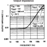
Referring to the original question, it seems to me that a large electrolytic output capacitor is useless at least in the small signal range, because the regulator output impedance is small compared to that of even a "low ESR" capacitor type.

7800.PNG

AC load currents or transients that excite the regulator loop in the large signal range make the problem even more complex. The capacitor could absorb some of the transient charge but also extend the transient response.

A RC post filter could make more sense.
 

Referring to the original question, it seems to me that a large electrolytic output capacitor is useless at least in the small signal range, because the regulator output impedance is small compared to that of even a "low ESR" capacitor type.

View attachment 147017

AC load currents or transients that excite the regulator loop in the large signal range make the problem even more complex. The capacitor could absorb some of the transient charge but also extend the transient response.

A RC post filter could make more sense.

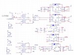
I have smaller caps in parallel. this is the schematic, I use smaller caps in parallel to guaranty parasitic remain low at high frequency. I never trust the big caps. I am laying out the board and should be able to send it out tomorrow.

Linear regulator schematic.JPG

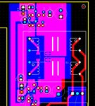
Part of the layout is shown below:

Linear regulator layout.JPG


You can see I have 0.1uF ceramic cap within 0.1" at both input and output of the regulators, I have 10uF and then 1000uF in parallel. I have both power and ground planes so it's good to hundreds of MHz. The output only have 10uF, the big caps is on the preamp board.

Yes, I have 5ohm resistor in series before the 1000uF cap on the preamp board. I want to keep those close to the preamp circuit so I don't pick up any noise along the wires.
 

Hi,

Safety first: I assume you didn´t care about safety regulations according creepage distance and air gap. It seems way too close.

I´m missing the filters on the mains side.

With your circuit you get short, but heavy current peaks at the rectifier, along the wires to the capacitors and back via GND plane.
This causes heavy magnetic field and voltage drop - even on the GND plane.
And the long and unsymmetric wiring makes it somehow a good antenna for EMI.
With a series inductor you may keep this pulsed currents lower, softer and more spread in time.
This should give a benefit in "quiet" supply rails and even GND.

Your circuit is very wide, in my eyes. I assume about 70mm. Are you sure this is good for several 100MHz?

Don´t get me wrong. Your circuit surely is a great benefit against usual audio amplifier power supplies.
But it seems: you want to design the best supply you can have, don´t you?

Klaus
 

Clearance and creepage is sufficient for 120 VAC, although it could be easily doubled.

I have smaller caps in parallel. this is the schematic, I use smaller caps in parallel to guaranty parasitic remain low at high frequency. I never trust the big caps.
10 µF looks reasonable. You discussed to use 1000 µF output filter in post #1. I agree that it's better suited as a post filter with series resistor.
 

Safety first: I assume you didn´t care about safety regulations according creepage distance and air gap. It seems way too close.
I do care, The only place I have question is the AC input connector that is 3.96mm pitch. The connector is spec for 400VDC, My first instinct is it's good for 125VAC ( we are not 220VAC). But that's a good point, maybe I should look up a 5mm pitch connector. The rest of the traces are covered with silk screen, it's not a problem.
I´m missing the filters on the mains side.

With your circuit you get short, but heavy current peaks at the rectifier, along the wires to the capacitors and back via GND plane.
This causes heavy magnetic field and voltage drop - even on the GND plane.
And the long and unsymmetric wiring makes it somehow a good antenna for EMI.
With a series inductor you may keep this pulsed currents lower, softer and more spread in time.
This should give a benefit in "quiet" supply rails and even GND.
I already have inrush current limiter before the connector. BUT, this is not a problem, those are only 6VA transformers, winding is small, with inductance, how much in rush current can you get? You only have current spike at the first 1sec or so. My amp has SS output relay designed in to block the output for the first 2sec.

There is no EMI concern to talk about. For one, this is a low current circuit, even the 5V is to power up the motorize remote small circuit. If you look at the layout, all the current return path are through capacitor that is very close by to the regulators. Also, I use power and ground plane, the loop area of the current path is very small to talk about EM emission.

Talk about EMI, the main transformer is a 500VA huge transformer, before I added the inrush limiter, the power switch lasted a whole 3days before it fried!!!!


Your circuit is very wide, in my eyes. I assume about 70mm. Are you sure this is good for several 100MHz?

Don´t get me wrong. Your circuit surely is a great benefit against usual audio amplifier power supplies.
But it seems: you want to design the best supply you can have, don´t you?

Klaus

This is power supply, I just have to make sure it provide clean power to power even RF circuits. I designed a lot of pulse amps of about 1nS rise time in early 90s with through hole transistor and through hole components. They are all 0.1" spacing minimum. I have confident this layout technique is good for over 100MHz design.


I'll look into the 5mm pitch connector, then I don't have to think about cleaning so much or paint over the contacts.

Thanks
 
Last edited:

Hi,

connector: Dot worry about the 3.96mm. Your PCB layout is much less than 3.96mm spacing.
If you have: try a high voltage at the connector and see where the spark is. I assume it´s not at the connector.

***
Current peaks:
I don´t talk about transformer inrush current. I talk about the current from transformer secondary through rectifier to capacitors and return.
There is a peak every halfwave. For a short time. And since you designed this path fast and low impedance -- the current peaks will be high.
Additionally the forward path and the return path is not symmetric, thus they can´t cancel out (like it does with twisted pairs).

Klaus

As I said, all the trace are covered with silk screen. They are good for 500VDC.

No, there will not be much spikes, this is only a 6VA transformer, the small wire and many turns will give plenty of inductance already. If anything, the other 500VA transformer will be a lot worst. That's where I was talking about using fast bridge rectifier.

Also, I explained already, I looked at the current path, with bypass caps so close by, with ground and power planes, the current LOOP area is very small, EM is very limited. I worked as Signal Integrity engineer in a contract for KLA Tancor designing layout for really high current, high density circuits. Never have any problem. Remember the total flux emitted is the flux density times the loop area. It is not important to have high flux density IF you have very small loop area.
 
Last edited:

Status
Not open for further replies.

Part and Inventory Search

Welcome to EDABoard.com

Sponsor

Back
Top