Continue to Site

Welcome to EDAboard.com

Welcome to our site! EDAboard.com is an international Electronics Discussion Forum focused on EDA software, circuits, schematics, books, theory, papers, asic, pld, 8051, DSP, Network, RF, Analog Design, PCB, Service Manuals... and a whole lot more! To participate you need to register. Registration is free. Click here to register now.

Light lit when motor rotate

Status
Not open for further replies.

PA3040

Advanced Member level 3
Joined
Aug 1, 2011
Messages
883
Helped
43
Reputation
88
Reaction score
43
Trophy points
1,308
Activity points
6,936
Dear All Have a nice day

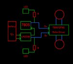
I make a line follower robot using Arduino Nano and TB6612FNG Motor driver. It is working but only issue is when the motor rotate manually that power goes to LED near 7805 regulator . please advice how should I manage to stop it

my reference schismatics is attached

I am using LM2695 regulator instead of the schismatics power supply

Please advice

Thanks in advance
 

Attachments

  • 3pi-schematic.pdf
    470.2 KB · Views: 100

Hi,

I think the schematic may be incomplete or someone threw a few blocks onto a screen and left them that way, also there are multiple pins connected to thin air for example.

Do all you uC people have some issue with drawing a normal schematic that isn't painful to interpret? I'm beginning to think so. ;)

At least it's not some clipped nonsense where all the poster shows is 1 input pin and nothing more yet asks for help because the circuit's a company secret.

I'm guessing that if this is your circuit and you don't know how to remove the LED with no name near a 7805 with no name - Are they (hopefully) D5, the one near the I think it's a 7805 with no label? - maybe no one else can help either.

What is the LED doing? Is it just a visual indicator to show the boost is on or is it some kind of minimum load for the boost converter or is the LED there to do something else? What is the 5.1V Zener needed for - is it really necessary to drop a few volts for an LED or is it some kind of protection?

Simple solution, without knowing what function D5 has - remove it and calculate a dropping resistor to drop the equivalent voltage or put a few 0.7V diodes in series to make up the voltage drop of the LED.
 
  • Like
Reactions: PA3040

    PA3040

    Points: 2
    Helpful Answer Positive Rating
When you spin an ordinary motor manually it becomes a generator. Evidently it produces enough voltage such that it travels back through circuitry, to light an LED.
 
  • Like
Reactions: PA3040 and d123

    d123

    Points: 2
    Helpful Answer Positive Rating

    PA3040

    Points: 2
    Helpful Answer Positive Rating
When you spin an ordinary motor manually it becomes a generator. Evidently it produces enough voltage such that it travels back through circuitry, to light an LED.

I hadn't understood how literally they may have meant rotate manually. Thanks.
 
  • Like
Reactions: PA3040

    PA3040

    Points: 2
    Helpful Answer Positive Rating
Hi PA3040,

Between the schematic and Brad's observation: What about a Schottky diode at the output of the 7805 blocking the reverse voltage (if actually generated by hand turning the motor) if a few 100mVs can be spared? Is the motor a 5V one that will work fine with ~4.6V?
 
  • Like
Reactions: PA3040

    PA3040

    Points: 2
    Helpful Answer Positive Rating
Dear All Thanks you very much for the replies

Please see the attached block diagram which is about my robot , Can we able to identify the solution to the issue i explained in my first post

When I rotate motor manually both LED light up .What is the best solution that we can apply

Please advice
 

Attachments

  • led.jpg
    led.jpg
    222.4 KB · Views: 146

Hi,

May I ask:
* why you rotate the robot manually? --> don't rotate it
* and what's the problem of light up LEDs in this case? --> don't care about the LEDs

Klaus
 

Dear Klaus Thanks for the reply

I this it is poor design . Some lack of engineering

Please and engineering solution
 

Hi,

I agree with Klaus, so don't rotate it ;) I guess this need is about predicting and protecting against what users may do with the device when left unsupervised by responsible adults.

Right now, rather than LEDs lighting up I'd worry more about sending a reverse voltage through drivers and regulators, especially the 7805 which isn't designed for that.

Not sure what the motor driver does so this is just from looking at the schematic you posted. Again, tried and tested solutions: put Schottky diodes from the two regulator outputs to the driver supply pins. Alternatively, maybe try diodes on the driver outputs and in this way block the reverse voltage from going through the driver back to the LED; it should work unless there's a polarity reason why that can't be done.
 

Hi,

I this it is poor design . Some lack of engineering
I can´t see this.

Tell me if I´m wrong: The robot is made to move by itself. So moving it by hand is mistreating the robot.

Klaus
 

Railway level crossing accident due to careless drivers . So we can't tell them stop cross the track while train is coming but we should give a solution . My case is not like that but as a engineering body we should have a solution

One solution as per d123 pointed out, a schottky diode apply output of regulator

Hope more solution
 

Status
Not open for further replies.

Similar threads

Part and Inventory Search

Welcome to EDABoard.com

Sponsor

Back
Top