Continue to Site

Welcome to EDAboard.com

Welcome to our site! EDAboard.com is an international Electronics Discussion Forum focused on EDA software, circuits, schematics, books, theory, papers, asic, pld, 8051, DSP, Network, RF, Analog Design, PCB, Service Manuals... and a whole lot more! To participate you need to register. Registration is free. Click here to register now.

Search engine for transistors / transistor comparator?

Status
Not open for further replies.

asrock70

Full Member level 4
Joined
Oct 9, 2010
Messages
201
Helped
5
Reputation
10
Reaction score
5
Trophy points
1,298
Activity points
3,252
Search engine for transistors / transiotor comparator?

I need to find a MOSFET transistor according to its switching speed and other parameters
Or need equivalent MOSFET, again with an emphasis on switching speed.
There is something like that?

What I'm looking for
Type of Transistor: MOSFET
Type of Control Channel: N -Channel
Maximum Power Dissipation (Pd): 170 W min
Maximum Drain-Source Voltage |Vds|: 400 V min
Maximum Gate-Threshold Voltage |Vgs(th)|: 5.5 V
Maximum Drain Current |Id|: 9 A min
Maximum Drain-Source On-State Resistance (Rds): 0.45 Ohm max
Ciss max 1920pF
td(on) max 11ns
tr max 14ns
Qg(on) max 60nF

After one hour of searching I found only one IXFH12N50F , but price in unacceptable
 

Re: Search engine for transistors / transiotor comparator?

according to its switching speed
"Time" as a search parameter is not helpful since all MOSFETs between different manufacturers are tested at different operating conditions. Even MOSFETs from same manufacturer but different technology is tested with different conditions.

Infineon CFD and CFD7 series (fast body diodes) has many MOSFETs that fulfill all your conditions.
 

Re: Search engine for transistors / transiotor comparator?

You're probably not going to find switching speed, the rise /
fall times and the delay depend on FET and not-the-FET
elements (driver output impedance, any interposed gate
resistors, the FET Cgs and Cgd and how the load may
want to swing (inductive? Resistive? Capacitive?).

There are "chooser" tools at any distributor and likely
most vendors (maybe not the third-tier ones), as far
as they go. But you may have to focus more on the
low level attributes (Cgg or Cdg) if you're after speed.

And of course a GaN FET will beat almost any MOSFET,
certainly any MOSFET of equivalent Ron and BVdss
in this respect.

If you say your td=11nS is just the time from zero to VT
and a 4V VT is roughly-right, that makes
I=C*dV/dt=1920E-12*4/11E-9=0.7A. No prob for any
usual MOSFET driver. But you probably want to target
fully-driven (10V) or more like 1.5A - 2A. Still sane.

EPC is all over the media with a vehicle radar PR push
where they made a 1nS FWHM pulse using one of their
GaN FETs. That's sporty. And they claim to be
approaching price parity. Of course this is EPC and
they claim lots of stuff. But a large amount of it appears
to be true.
 

Re: Search engine for transistors / transiotor comparator?

No prob for any usual MOSFET driver

This MOSFET is in to second stage two transistor Class F amplifier on frequency over 10MHz and is drive from MOSFETm if I'm not mistaken IRF510.

The colleague suggested first stage for parameters gate IXFH12N50F, with this transistor amplifier works great. Unfortunately, I did not notice, IXFH12N50 not IXFH12N50F and not IXFH12N50A.
And price of IXFH12N50F in not good for economy of design
 

Re: Search engine for transistors / transiotor comparator?

Hi,

Switching Mosfet .... and 170W power dissipation ... this is quite unusual.
May I ask why it needs that high power rating?

9A and 0.45 Ohms just gives 36.5W with 100% duty cycle.
It's very unlikely that there is more than 100W switching loss.

Klaus
 

Re: Search engine for transistors / transiotor comparator?

May I ask why it needs that high power rating?
If everything is okay for nothing,because the power is consumed in the load.
Unfortunately in the application unexpected disconnection of the load is a common thing.
If load is disconnected , power is reflected from the end of the lead and ...
Yes in design is a standing wave detector that switches off the device in this case, but all have any time delay (may be 1ms) and with safety considerations, we want the transistor to survive 170W PD for time 10ms.
It would probably be less, but we leave a reserve, because 170W in for Tc 25C and we calculate ( estimate) for 50C.

IXFH12N50F is for me good choice, but Farner say No Longer Manufactured mouser hewve in stoct but price 10.79$ for 10pcs is not good, TME has no offer.
According to the manufacturer is produced , it is generally not good to use a transistor for which there is no or we can not find alternative.


I look on IPW60R125CFD7

MOSFET dv/dt ruggedness 120V/bs IXFH12N50F 20
RDS(on) 104mohm IXFH12N50F 400
Ciss 1503 pF IXFH12N50F 1870
Qg 36 nC IXFH12N50F 54
but
td(off) 66ns 400V 8.1A IXFH12N50F 28ns for 250V 6A

Why ?
 

Re: Search engine for transistors / transiotor comparator?

Hi,

the transistor to survive 170W PD for time 10ms.
if you look into the datasheet for PD = 170W, then this means continous power dissipation.

if you just want it for 10ms you should look in the SOA chart of the transistor.
I assume most 10W rated transistors will withstand 170W for 10ms. (not confirmed)

Klaus
 

Re: Search engine for transistors / transiotor comparator?

td(off) 66ns 400V 8.1A IXFH12N50F 28ns for 250V 6A

Why ?
Again, can you see that they are tested at different conditions ? In other words, switching times manufacturers give are note comparable.
Between this particular 2 MOSFETs you are presenting, the Infineon one is faster than IXYS one because it has lower charges at higher voltage & current ratings.
The only "drawback" in terms of speed the Infineon one has, is its high internal gate resistance <<-- reason of the high delay time.

If you want to convince yourself, test them both at the same conditions (or simulate them) at the same conditions.
 

Re: Search engine for transistors / transiotor comparator?

OK loon on page 7 in datasheet IPW60R125CFD7
Dagram 1: Power dissipation
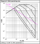
For 25C 92W for 50C 73W, if we look on Diagram 2: Safe operating area VDS=20V Io=1A we are in 10ms area and 92W transistor have for 20W SOA only 20W for time 10ms.
Sometimes can be 170W 10ms problem, even for 92W transistors.
Generally yes.
Maybe it might not be 170W,
1. Conduction lost , for example 6W.
2. Switching lost for example 7W
3. Gate charge lost may be 1W
14W lost if all power go to load, i.e if we will calculate for Tc=50 we need 30W transostor for idela case
if all power go as standig wave back ......
 

Re: Search engine for transistors / transiotor comparator?

Hi,

the shown transistor is somehow different regarding power dissipation.

From the case it should be able to dissipate way more heat. The R_th_JC is extremely high for such a big case. Thus I assume there is a relatively small die inside ... and the package is just that big because of the rated voltage.

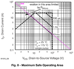
The two SOA charts show about the same .. there are just minor deviations at high currents. This makes no snese to me, because the SOA should depend on P_tot and not from current.
I see about 3W for DC at 25°C as well as 80° Tc
I see about 9W for 10ms at 25°C as well as 80° Tc
Both SOA values do not match the Power dissipation chart, which shows about 90W at 25°C and 50W at 80°C.
(80°C - 25°C) / (90W -50W) = 1.375K/W which almost perfectly meets the 1.36K/W given in the datsheet for R_th_JC.

--> I don´t trust the SOA curves, but for sure I can´t give you a guarantee on any values.

***
--> Either rely on the datasheet values or contact the manufacturer.

***
Sorry that I can´t help you with this.

Klaus
 

Re: Search engine for transistors / transiotor comparator?

I see about 3W for DC at 25°C as well as 80° Tc
I see about 9W for 10ms at 25°C as well as 80° Tc
Both SOA values do not match the Power dissipation chart, which shows about 90W at 25°C and 50W at 80°C.
(80°C - 25°C) / (90W -50W) = 1.375K/W which almost perfectly meets the 1.36K/W given in the datsheet for R_th_JC.
Sure it matches.

The SOA curve starts to be power limited (at DC) at the same value the Power dissipation graph (Diagram 1 shows).

Diagram 2 (Tc=25ºC):
The graph starts to be limited at about ~18V*5A~90 W <<-- same as Diagram 1 shows.

Diagram 3 (Tc=80ºC):
The graph starts to be limited at about ~13V*4A~52 W <<-- same as Diagram 1 shows.
 

Re: Search engine for transistors / transiotor comparator?

Go to octopart . com and search, you can put in most of the parameters you desire and rank by cheapest

I got SIHP14N50D-GE3 & FQP13N50C ( $1.89) as the two cheapest, they are TO-220 - but there are heaps of others

https://octopart.com/search?category_ids=4229&q=500V mosfet&start=0&specs2.497.numbers=190&specs2.497.numbers=192&specs2.497.numbers=195&specs2.497.numbers=200&specs2.497.numbers=205&specs2.497.numbers=208&specs2.497.numbers=220&specs2.497.numbers=250&=&sort=median_price_1000&sort-dir=asc


you're welcome

EP.
 

Re: Search engine for transistors / transiotor comparator?

Hi,

Sure it matches.

The SOA curve starts to be power limited (at DC) at the same value the Power dissipation graph (Diagram 1 shows).

Diagram 2 (Tc=25ºC):
The graph starts to be limited at about ~18V*5A~90 W <<-- same as Diagram 1 shows.

Diagram 3 (Tc=80ºC):
The graph starts to be limited at about ~13V*4A~52 W <<-- same as Diagram 1 shows.

It took a long time to see what you mean.
At first I couldn´t reproduce your values.
You wrote: 18V*5A --> but you meant: 18A*5V. Now I see your point and agree with you in this.

But what´s still confusing me: Power generates heat.
Let´s say 90W... and for my understanding it should not matter if the 90W come from 18V*5A or 18A*5V....but the chart says: it matters.
Here the IPW60R125CFD7 SOA chart.
SOA2.png
The SOA line doesn´t follow a constant power line.

****

this is what other datasheet SOA charts show (Here IRF510):
SOA1.png
The SOA graph follows a constant power line.

****
I have no explanation for this behaviour. Thus I still doubt the IPW60R125CFD7 datasheet SOA chart.

Klaus
 

Re: Search engine for transistors / transiotor comparator?

switching power mosfets have a little discussed failure mechanism as the Vds goes up, under linear operation, esp above 100VDC. A google search will likely provide some papers on the matter.

In any event the SOA is often done at 25C junc - i.e.pulse tests, a more useful graph would be at 100C junc.
 
  • Like
Reactions: KlausST

    KlausST

    Points: 2
    Helpful Answer Positive Rating

Re: Search engine for transistors / transiotor comparator?

Let´s say 90W... and for my understanding it should not matter if the 90W come from 18V*5A or 18A*5V....but the chart says: it matters.
Here the IPW60R125CFD7 SOA chart.
Like Peasy said, for the DC case in that SOA chart, the line they are plotting is in linear operating mode (i.e. saturation region). It is not limited by the thermal dissipation. The thermal dissipation limit line appears a bit in the 10ms case and increases as the pulses gets shorter.

Here is a quote from Infineon:
In linear mode operation, there is a risk of getting hot spots at low gate-source voltages due to thermal run away. This effect becomes more important for latest trench technologies with high current densities, where the “zero temperature coefficient” point of the transfer characteristic is shifted to higher drain
currents. More information can be found in the application note mentioned above "Linear Mode Operation and Safe Operating Diagram of Power MOSFETs"

Linear Mode Operation and Safe Operating Diagram of Power MOSFETs --> is the app note you already found
The quote I am giving is from here (page 10, point D)): https://www.infineon.com/dgdl/Infin...h.pdf?fileId=db3a30433b47825b013b6b8c6a3424c4

- - - Updated - - -

You wrote: 18V*5A --> but you meant: 18A*5V.
Yes, I wrote it wrong.
 

Re: Search engine for transistors / transiotor comparator?

Respectfully"
linear operating mode (i.e. saturation region)
is note quite the same thing, a device can be operating in a linear mode, but far from saturation.

We build fully controllable electronics loads, where often the fets are conducting 780mA at 60VDc applied ( i.e 47W per fet / TO-247 ) but are far from saturated - we need to use large die fets for this ( ~ 250W rating at 25degC ) with older technology cell structure as they are far more robust.

As far as we are aware IXYS are the only large scale suppliers of truly linear operation mosfets - with defined DC SOA.
 

Re: Search engine for transistors / transiotor comparator?

is note quite the same thing, a device can be operating in a linear mode, but far from saturation.
Seems to me that you are calling linear mode to the ohmic region, which seems contradictory to the 60VDS you have ? Otherwise, in your view you have 4 operating modes of a FET (cutoff, ohmic, xx, saturation).

Can you explain what you mean ?
I am using post's #15 document terminology, by the way.

- - - Updated - - -

often the fets are conducting 780mA at 60VDc applied ( i.e 47W per fet / TO-247 ) but are far from saturated
What "Vgs" do you use ?
 

Status
Not open for further replies.

Similar threads

Part and Inventory Search

Welcome to EDABoard.com

Sponsor

Back
Top