Continue to Site

Welcome to EDAboard.com

Welcome to our site! EDAboard.com is an international Electronics Discussion Forum focused on EDA software, circuits, schematics, books, theory, papers, asic, pld, 8051, DSP, Network, RF, Analog Design, PCB, Service Manuals... and a whole lot more! To participate you need to register. Registration is free. Click here to register now.

Momentum Substrate Files (ltd, slm) to Asitic tek file

Status
Not open for further replies.

Puppet123

Full Member level 6
Joined
Apr 26, 2017
Messages
356
Helped
22
Reputation
44
Reaction score
21
Trophy points
18
Activity points
3,059
Hello,

I have Momentum slm and ltd files that define a substrate in a process.

Is there an easy way to convert these into an ASITIC tek file, I want to design some passives in ASITIC but dont have the tek file.

Thanks.
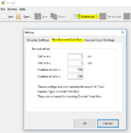
 

Thank you, will it work with default cell size and number of cell settings ? (1um, 256)
 

Thank you, will it work with default cell size and number of cell settings ? (1um, 256)

You can set this is in the m/matl Preferences dialog before export. But the ASITIC file is plain ASCII anyway, so easy to modify anything.

pref.PNG
 

Thank you, what I meant was, will the default setting allow the converted .tek file to work in asitic ?

Are those settings the default settings for asitic tek files ?
 

The cell size in the ASITIC example tech file is even larger (2µm), but of course it depends what geometry dimensions you will create/simulate.
As mentioned above, this ASITIC output from m/matl wasn't tested much, so no warranties of any kind that it works for your needs

BTW, in another thread you asked about transformer tutorials. When I implemented transformers for my RFIC Inductor Toolkit for ADS, I found this paper useful: https://pdfs.semanticscholar.org/b7b6/004fc2c9d05ff566799235794f519f28b3d2.pdf
 

Hello,

Thank you.

So if I use the cell size of 2um, I should be "safe" when using ASITIC ?

I am making mmwave inductors and transformers and they tend to have smaller dimensions.

So maybe 1um is better ? What do you think ?

Thank you.

Also thanks for the paper recommendation.
 

So if I use the cell size of 2um, I should be "safe" when using ASITIC ?

There is no "safe" value, the cell size determines how accurate the solver can place current/charge onto your metals. It really depends on your geometry details, and finer cell size allows more accurate modelling of high edge currents etc.

**broken link removed**

That said, 1µm is a typical value that often works, but if you create a balun with 5µm trace width then you need a finer mesh (smaller cell size).
 

Status
Not open for further replies.

Part and Inventory Search

Welcome to EDABoard.com

Sponsor

Back
Top