Welcome to our site! EDAboard.com is an international Electronics Discussion Forum focused on EDA software, circuits, schematics, books, theory, papers, asic, pld, 8051, DSP, Network, RF, Analog Design, PCB, Service Manuals... and a whole lot more! To participate you need to register. Registration is free. Click here to register now.
Is there a table to find the dimensions of all traces and microstrip elements to etch a planar array on a -say-1m x 1m copper clad board ? for 4GHz; for 12GHz ?
I can design such antenna array, which will have good performance in relatively wide bandwidth using any generic 1.0mm FR4 material. I expect that it would be difficult to manufacture it using DIY techniques.
Do you have more exact values of minimum and maximum frequencies? Minimum and maximum frequencies required to optimize antenna bandwidth.
for example something like 3.9 to 4.9 GHz for 4GHz antenna
and 12.1 to 12.5 GHz for 12GHz antenna
Maybe some other constraints, like substrate thickness, etc.
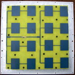
Agree. From my experience: good results for small array 8x8 patches at 10GHz, but board size was much smaller that 1 meter. I used aperture coupled wideband patches to solve FR4 er influence on resonant frequency problem.
1. Maybe for large array air may be used as dielectric, FR4 material will be on top of antenna. It may be examined in simulator.
2. Or maybe just put NE3210S01 on each subarray of corporate array to amplify signal. Self noise of each amplifier will not add up in-phase, kind of active array.
3. Or use ridge gap waveguide feeding network, but it will require PCB fab to manufacture.
Long ago I had a customer who created a 2x2 patch array on FR4 at (only) 2.4GHz. The array gain was about the same as a single patch, the theorectical extra gain was lost in the distribution network.
For larger arrays, and higher frequencies, the patch array on FR4 will be more like a dummy load ....
volker, no strict measurements done to my array. Totally understand your skepticism. I made many prototypes on FR4, and problem is classical patch is too narrowband. My single aperture coupled patch surely have more gain than array of two patches used in 10GHz door openers.
I thinked about this topic and here are two ideas:
1) use ridge gap waveguide on FR4. Can obtain results very similar to machined waveguide feeding network, low losses, can make modular construction using RGW to RGW transitions, so antenna may be assembled from blocks around 25x25cm. Although it will have many screws and washers. Washers may be replaced by thin PCB layer with cutouts or some similar structure.
2) use any wideband planar antenna, and put simple FET amplifier on each 4x4 subarray to compensate losses. Make it active antennas array.
Volker observation is the same to what I found for many years now..
You can use FR4 designing PCB circuits up to 6 GHz (hopefully), but FR4 frequency limitation designing good printed antennas is somewhere near 1.5 GHz.
This site uses cookies to help personalise content, tailor your experience and to keep you logged in if you register.
By continuing to use this site, you are consenting to our use of cookies.