Continue to Site

Welcome to EDAboard.com

Welcome to our site! EDAboard.com is an international Electronics Discussion Forum focused on EDA software, circuits, schematics, books, theory, papers, asic, pld, 8051, DSP, Network, RF, Analog Design, PCB, Service Manuals... and a whole lot more! To participate you need to register. Registration is free. Click here to register now.

Question about a car electric tester pen

Status
Not open for further replies.

mohsen 2012

Member level 4
Joined
Jul 3, 2012
Messages
70
Helped
0
Reputation
0
Reaction score
0
Trophy points
1,286
Activity points
1,796
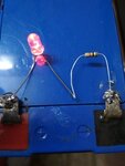
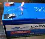
Hi guys , i want to know if can i use this simple circuit for testing car polarity wires without risk or no :

simple tester led.png

**broken link removed**

Thanks ☺
 
Last edited by a moderator:

Hi,

The problem with your circuit is, that LEDs can withstand only 5V in reverse polarity.
For this the resistor is no protection, it just limits the current.

The use of your circuit is to check polarity, thus it is not unlikely that the applied voltage is in reverse.
To protect the LED I recommend to connect a small signal diode (like 1N4148) in series with your resistor.

I also recommend to connect a resistor (same value as the currently used) to connect in parallel with the LED.
This even more protects the LED and prevents it from dim shining with low currents applied.

Klaus
 
  • Like
Reactions: d123

    d123

    Points: 2
    Helpful Answer Positive Rating
If you plan to check the polarities of the wirings coming out from the fuse panel (which is the most likely case), surely the wires have followed color standards commonly used in automotive industries (it depends on your countrry). In this case only the black wire will be used as the reference, which is connected directly to the chassis of the car, what means that in this case the polarity itself does not matter at all, since the negative battery terminal is connected to the car body. However, if your tester is for a more comprehensive application than the wiring already available in the vehicle (ie, a complete reworks), it is advisable to consider inserting a fuse in order to avoid a disaster in the event of the LED failure, which as being a diode, it could behave as a short circuit when burned - at least silicon diodes acts as such.
 

Hi,

The problem with your circuit is, that LEDs can withstand only 5V in reverse polarity.
For this the resistor is no protection, it just limits the current.

The use of your circuit is to check polarity, thus it is not unlikely that the applied voltage is in reverse.
To protect the LED I recommend to connect a small signal diode (like 1N4148) in series with your resistor.

I also recommend to connect a resistor (same value as the currently used) to connect in parallel with the LED.
This even more protects the LED and prevents it from dim shining with low currents applied.

Klaus
Good point. The reverse protection diode is necessary.
 

Yes there is a problem when i plug the black test lead to the negatve battery , i found that the negative signal is also present on the red test lead , same problem when connect red clop to the + battery !!!
So the tester is work like a jumper wire !!!
It can be burn the car ??????
I am really worry !! Because im already build it and work with it on my car !
 

What do you mean 'the negative signal is present on the red test lead'?
 

It would not burn the car if you take the precautions mentioned above, but if you intend to use this tester with the engine working, this could actually damage the LED, which does not handle high voltage transients, typical of a car battery bus particularly during ignition.
 

If the resistor value is sufficiently high, may be a 10K/1 watt, then a diode may not be necessary...an LED with 10K resistor can be used even with 220V mains AC for a short period of time with no issues, although the illumination on the LED may not be too impressive.
 

No led is going to turn on with a 10k resistor in series. At least not at 12 v.
 

Attachments

  • IMG_20180528_105602.jpg
    IMG_20180528_105602.jpg
    20.3 KB · Views: 100
  • IMG_20180528_105703.jpg
    IMG_20180528_105703.jpg
    32.3 KB · Views: 93

Industry standard is 10 megaohm input impedance for test equipment - this is to prevent damage to sensitive circuits in the automobile (a lot airbags have been triggered by people using analog meters and old test lights with incandescent light bulbs). You can find reasonably cheap multi-meters that have 10 megaohm impedance, I would get one of those and learn how to use it for working on your cars electrical system. Also there is no standard for automotive wire colors where I live (N.A.) - every car is different - black does not equal ground and red does not equal power so you want to make sure you are testing your wires with a meter.
 

Status
Not open for further replies.

Part and Inventory Search

Welcome to EDABoard.com

Sponsor

Back
Top