Continue to Site

Welcome to EDAboard.com

Welcome to our site! EDAboard.com is an international Electronics Discussion Forum focused on EDA software, circuits, schematics, books, theory, papers, asic, pld, 8051, DSP, Network, RF, Analog Design, PCB, Service Manuals... and a whole lot more! To participate you need to register. Registration is free. Click here to register now.

Flyback converter EMI vs capacitive touch buttons

Status
Not open for further replies.

kekon

Full Member level 3
Joined
Sep 19, 2002
Messages
155
Helped
5
Reputation
10
Reaction score
3
Trophy points
1,298
Location
Poland, Białystok
Activity points
1,493
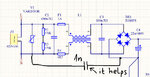
I have difficult problem with some device powered from offline SMPS flyback converter. The converter is based on Viper27H chip; 20W and has two outputs: 5V and 12V. It is powered from 230V AC with two wires (without earth wire).
The device contains 4 capacitive touch buttons (under 4mm glass plate). The power supply and device are placed on separate PCBs connected with 8-wire flat cable.
When i power my device from DC linear regulated power supply the touch panel works perfectly. But when it is connected to SMPS it becomes unresponsive. It is clear that there is some kind of EMI produced by SMPS that harms capacitive buttons. However, when the negative output terminal of SMPS is connected to earth, the problem disappears. Even when i connect the negative terminal to earth through 3.3nF capacitor it also helps. I added common mode choke to the converter, post filter but these solution simply don't work. It is really dufficult for me to solve the problem. I cannot use earh connection in my equipment as it is powered from two wire cable from 230V AC. Did anyone of you have similar problem ?
 

Hi,

I assume it´s the coupled switching noise that affects the touch button operation.
The touch button circuit works with tiny capacitance differnce and tiny charges .. thus your touch_button_GND should be rather clean referred to EARTH_GND.

I simple common mode filter won´t work.
It just generates high series impedance for switching noise... but this is only one half of the filter. To work properly it additionally needs (way) less impedance to ERATH_GND to be able to suppress the noise. See it like a voltage divider: high series impedance --> low EARTH_GND_impedance.

If you can´t make a low_impedance_EARTH_path, then I see only one solution: Use a more clean power supply.

*****
Is the glass mounted in a metal case or metal frame --> then a (capacitive) connection to the case (or frame) may help. I dont know how reliable.

Klaus
 

The touch panel is mounted in a plastic box and glued directly to the glass. The equipment is itself earthed and has a metal case. But there is no way to connect the "minus" terminal of the power supply to the earth.
Previously, the equipment contained capacitive "transformerless" power supply and there were no problems with EMI but the touch panel PCB circuit was often damaged due to high leakage currents from 230V AC mains. That's why i had to replace it with other type with galvanic isolation.
 

Did you try state-of-the-art "Y" capacitors between secondary and primary ground or mains L and N wire? Most off-the-shelf DC/DC converters have it.
 

Did you try state-of-the-art "Y" capacitors between secondary and primary ground or mains L and N wire? Most off-the-shelf DC/DC converters have it.

Of course.
There is an Y capacitor between primary and secondary GND and also two X capacitors at L and N wires (one before the CMC choke and the second behind the choke).
I always add these capacitors in every SMPS design.
 

Hi,

is there a fix connection with mains, or a plug that can be turned?

Show your filter and power supply circuit.

Klaus
 

I've just connected small capacitor (1nF) between primary GND and one of the power AC supply mains - it seems to solve the problem (it doesn't matter if it is N or L)
I can't show the whole schematic for it is confidential.
 

Attachments

  • schematic.jpg
    schematic.jpg
    46.3 KB · Views: 169

is there ceramic cap at the output of acdc?

How close the pcbs to each other?

maybe try to put shield between the pcbs. shield connect to gnd of acdc pcb or gnd of button pcb or N
 

is there ceramic cap at the output of acdc?

How close the pcbs to each other?

maybe try to put shield between the pcbs. shield connect to gnd of acdc pcb or gnd of button pcb or N

Yes, there is 100nF ceramic cap. The PCBs are far from each other (connected through 8-way flat cable 0.5m length).
I also put the cable through toroidal ferrite core (3 turns) but without effect.
I see that adding a 1nF capacitor as shown in the previous picture solves the problem (however, i wonder why it works in this way....)
 

I see that adding a 1nF capacitor as shown in the previous picture solves the problem (however, i wonder why it works in this way....)

far?

the issue, i think, is parasitic capacitive link between pcbs

the gnd net maybe have big poly on acdc pcb, so this cap changing somehow the picture of cap links, so it helps

- - - Updated - - -

far is 0,5m?
 

I see that adding a 1nF capacitor as shown in the previous picture solves the problem (however, i wonder why it works in this way....)
Could be that 1nF resonates with the CM choke near the flyback's switching frequency, causing it to better block common mode EMI.

- - - Updated - - -

Of course.
There is an Y capacitor between primary and secondary GND

Are you sure you connected it to the proper nodes? It's not necessarily so straightforward, depending on how the transformer is built.
 

I don't think there is resonance between 1nF and the CM choke because i connected also other capacitors like 2,2nF in series with different resistors: 47R, 100R and 510R. In all three cases, it worked well. It there was resonance the 510R resistor would completely attenuate it.
 

Your only hope is to significantly "quieten" your converter. A high level of snubbing on the o/p diodes, and across the Tx pri ( RCD ) with perhaps another snubber across the D just mentioned if the leakage is high. Also reduce the turn-on and turn-off gate drive until the fet has an additional 5-10 deg C rise. THEN you can play with external CM chokes, one on each DC port and one on the RHS of the mains bridge...

I mention the above because the 1nF "solution" above will likely cause a fail for EMC on the conducted and possibly radiated emissions .....
 

I added snubbers across output diode and also additional snubber on the mosfet drain. These solutions didn't work. The power dissipated in the snubber on the drain was too high.
There is no way to get access to mosfet gate as the transistor is internal part of the Viper27H and there is no access to the gate.

I mention the above because the 1nF "solution" above will likely cause a fail for EMC on the conducted and possibly radiated emissions

I realize that. That's why it is connected in series with resistor.
The capacitor will be removed for the EMI test and connected again after it ;)
 

Respectfully, your comment:
The capacitor will be removed for the EMI test and connected again after it ;)

is some what less than professional, and in the EU, USA and a number of other countries, would be a confession of intent to break the law, i.e. a criminal offense.

Better to strive for a technical solution that will increase your reputation rather than tarnish it ...

- - - Updated - - -

try 10nF 630VDC caps across the bridge diodes, with 180E 0.5W in series with each cap...
 

is some what less than professional, and in the EU, USA and a number of other countries, would be a confession of intent to break the law, i.e. a criminal offense.

The device will not be in mass production - it will be used for private purposes, so the "criminal offense" in not the case.
 

Hi,

Wow..
You do a true EMI test ... for a single, privatly used application.

Klaus
 

Hi,

Wow..
You do a true EMI test ... for a single, privatly used application.

Klaus

Why not ?
I have a free unlimited access to one. Just for curiosity. Gaining new experiences is not a bad thing, is it ?

try 10nF 630VDC caps across the bridge diodes, with 180E 0.5W in series with each cap...

I tried it as well, no success...
 

Hi,

Why not ?
I have a free unlimited access to one. Just for curiosity. Gaining new experiences is not a bad thing, is it ?

Lucky you.
I appreciate the effort. You surely gain experience. Good job.

Klaus
 

The problem also disappears when I hold in hand the flat cable connecting the two boards (the cable has of course isolation). This creates small capacitance between cable wires and earth.
 

Status
Not open for further replies.

Similar threads

Part and Inventory Search

Welcome to EDABoard.com

Sponsor

Back
Top