Continue to Site

Welcome to EDAboard.com

Welcome to our site! EDAboard.com is an international Electronics Discussion Forum focused on EDA software, circuits, schematics, books, theory, papers, asic, pld, 8051, DSP, Network, RF, Analog Design, PCB, Service Manuals... and a whole lot more! To participate you need to register. Registration is free. Click here to register now.

2 phase Nonoverlapping clock generation can't not delay

Status
Not open for further replies.

sa126997

Newbie level 4
Joined
May 2, 2018
Messages
7
Helped
0
Reputation
0
Reaction score
0
Trophy points
1
Activity points
49
I trt to make non overlapping clock but it wave can't delay i am so confused
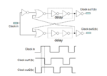
np.PNG


This is my code
PHP:
*

.GLOBAL GND
+        VDD

.SUBCKT inv in outI
MmnI outI in GND GND n_18 W=0.47u         L= 0.18u
MmpI outI in VDD VDD p_18 W=0.94u         L= 0.18u
.ENDS


.SUBCKT nor C1 C2 out
MN71   out        C1   GND      GND n_18 W=10.00u  L= 0.18u
MN72   out        C2   GND      GND n_18 W=10.00u  L= 0.18u


MP71   out       C1   net06     VDD p_18 W=10.00u  L= 0.18u
MP77   net06     C7   VDD       VDD p_18 W=10.00u  L= 0.18u
.ends


.SUBCKT   ft CK ck1 ck2  
XINV1     CK  N1            inv
XNOR1     N1  N6    R1      nor

XINVL2     R1  N2           inv
XINVL3     N2  N3           inv


XINVUU     N3  ck1          inv


XNOR2     CK   N3   R2      nor

XINVL5     R2  N5           inv
XINVL6     N5  N6           inv


XINVDD     N6  ck2          inv
.ENDS

Xft CK ck1 ck2               ft
VGND    GND    0v    DC=0v
VVDD    VDD    GND   DC=1.8v
VCK     ck     GND   PULSE 1.8 0 100u 0u 0u 50u 100u 
********************************************************* 
.PROT
.lib "/cad/cell_library/cic18/model/model/cic018.l" TT
.UNPROT
.MEAS TRAN Pmax AVG POWER FROM = 0us To =400us
.TEMP 27
.OPTION POST ACCURATE=3 METHOD=GEAR
.TRAN 0.1u 400us
.end

and this is my wave
沒有延遲.JPG
 
Last edited:

I think you need to zoom much more.

The delay of the inverters is miniscule compared to your 100-us period time. Those inverters will delay the phase by some fraction of ns.

Either increase the frequency of your system, or zoom in on the edges, or insert a looooong inverter chain to delay properly compared to clock frequency.

You can also use an inverter > R-C load > inverter as a delay element.

So can I put this on the end of my circuit to delay?dl.PNG
 

On your 1st attachment into the Delay blocks insert the Cdelay like on your last figure, between the inverters. At the top and the bottom branches too.
Or as jjx said, you can use RC too between the 2 inverters, or a long inverter chain too.
 

Status
Not open for further replies.

Part and Inventory Search

Welcome to EDABoard.com

Sponsor

Back
Top