Continue to Site

Welcome to EDAboard.com

Welcome to our site! EDAboard.com is an international Electronics Discussion Forum focused on EDA software, circuits, schematics, books, theory, papers, asic, pld, 8051, DSP, Network, RF, Analog Design, PCB, Service Manuals... and a whole lot more! To participate you need to register. Registration is free. Click here to register now.

Applying KVL on an NPN BJT.

Status
Not open for further replies.

Jayce

Newbie level 5
Joined
Mar 24, 2018
Messages
8
Helped
0
Reputation
0
Reaction score
0
Trophy points
1
Activity points
110
EB.png

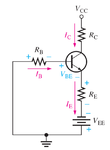
From the figure above. On the book I'm reading, KVL was applied from around the base-emitter circuit. (From Vee rotating clockwise.) The equation resulted to:

Vee + Ib*Rb + Vbe + IeRe = 0.

But looking at the placement of the battery, shouldn't it be: Vee - Ib*Rb - Vbe - IeRe = 0?

Note: The book follows conventional current for the flow.
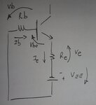
 

Perhaps part of the question is to realize that the answer could be Vee as having negative value, apart of its orientation drawn on the circuit.
 

No - it is correct. The current is considered as to flow from the positive to the negative end of the resistors, the B-E junction and the voltage source.
 

Just place the voltage arrows across each element to see the equation

Vee + Ib*Rb + Vbe + IeRe = 0

is wrong. Doesn't matter the numerical value of voltage and current. The result is symbolic and take into account the choosen polarities.

Transistor.jpg
 

Status
Not open for further replies.

Similar threads

Part and Inventory Search

Welcome to EDABoard.com

Sponsor

Back
Top