Continue to Site

Welcome to EDAboard.com

Welcome to our site! EDAboard.com is an international Electronics Discussion Forum focused on EDA software, circuits, schematics, books, theory, papers, asic, pld, 8051, DSP, Network, RF, Analog Design, PCB, Service Manuals... and a whole lot more! To participate you need to register. Registration is free. Click here to register now.

I need a short single "BEEP" circuit

Status
Not open for further replies.

yair-1

Newbie level 4
Joined
May 20, 2018
Messages
5
Helped
1
Reputation
2
Reaction score
1
Trophy points
3
Activity points
43
Hi
For longboard that I've built, I want to add a "beep" sound while turned on.
It works on self made 42v battery, but i can take any voltage on steps of 4.2v, or
add a step down converter.
The sound should be short, about half sec.
Any one can help me with a circuit for it?
Thanks
 

When you say "longboard" I assume you mean a skateboard? What is it you are "turning on"? All we know is that you have a 42V battery.
 

Hi,

A simple solution that is pretty cowboyish but should be effective: a 555 and a buzzer (I'd have to think about how to make a beep, more than a buzz. You can get transistors to make fun noises with a little loudspeaker - you should look into it; there's also a 555 "musical organ" you could adapt easily, unless a tinny noise is not what you're aiming at. You'd have to play with it to see if you get a nice sound out of it.)

The 555 has a "defect" that it turns on at power-up (unless you control that with a POR). A one-shot will trigger at every power-up (to many people's annoyance) and you can set the length of the "beep" with a resistor and a capacitor. Generalising a bit, by connecting the output of the timer to a buzzer it will do what you want and I would be surprised if the 555 defect ever lets you down, it's very reliably triggered by power-up events - I abuse that defect/feature sometimes. Of note is that 555 first output high as power-up is sort of double the length it is during normal operation.

TOY ORGAN Circuit It looks easy to adapt. Remove four buttons and four resistors. Remove the last button and connect directly from the bottom end of VR1 to the top of C1. Pin 5 should really have a 100nF capacitor to ground. The organ is an astable timer circuit, not the same as my suggestion of a monostable. It could be accomplished with another timer to make the "organ" beep briefly but that would be a solution with too many parts. I would use a monostable and a buzzer or a speaker if you wish and let it trigger at power-up, timeout and then be silent until next power-up.

If you have 4.2V steps, then you can choose whatever up to about 16V maximum for the 555 timer.
 

Hello yair-1,
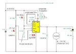
Please see picture below:

BEEPER

In the circuit above, the 555 Timer is configured in Astable mode.
When ever power is applied, the output at Pin 3 will trigger the piezo transducer
with a short beep and the LED will light up and stay on.
Therefore giving the beep you require and at the same time give you the power
"ON" LED indication, up until you turn everything off.
Pin 4 on IC1 must NOT be connected to anything.
If you can reduce the input voltage as stated by d123, then you can omit R1 and
D1 from the circuit and connect your lowered voltage directly to R2.

I hope the above helps.
Regards,
Relayer
 

Hi,

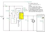
I had a quick play to check earlier on a breadboard and here is a schematic if you want to use it with a buzzer. It's failsafe and beeps every time you power up. Easy to modify beep time and volume. You can use 1/4 Watt resistors and 25V capacitors should be more than enough for this kind of thing. The diode if used could be a 50V/1A that will more than do. e.g. SS14 Schottky, 1N4148 signal diode, 1N4007 rectifier diode - any will do, last two have 0.7V drop, SS14 is maybe 300mV.

longboard power up beep circuit.JPG
 

Hi,

Just in case... To be able to use the LED with a 4.2V to 16.8V input voltage and not stress the LED nor worse burn it out without having to change any components each time, R1 would need to be 700R upwards, 820R or 1k is fine.
 

I never seen a powered longboard so, I looked in Google. Some cost thousands of dollars and have two 1kW motors!
 

Yes. as much as you will use a higher quality parts, as much it cost more. my battery pack is 10s4p. 40 cells of 18650 Li-Io. The other components, well, this is an issue for a new thread....
 

sorry, why an astable would be necessary? I thought a monostable would work better, isn't it? or even a simple transistorized circuit with a blocking capacitor at base would do the job nicely...
 

Well, just build the BEEPER one from above. The sound is very low and its not single. It's comming on every 3 secconds. Need it to be much louder and only one beep.
 

Well, just build the BEEPER one from above. The sound is very low and its not single. It's comming on every 3 secconds. Need it to be much louder and only one beep.

Try the circuit in post #5... It works. I already told you so, sorry you missed that.
It is extremely reliable, if not in fact flawless.
You can make it louder or quieter with a capacitor - C6 (try 10uF if 1uF isn't loud enough at 4.2V to 4.8V, 8V will definitely be loud enough).
It only beeps once and for half a second - like you requested.
I did that circuit for you, enjoy it, it would be a waste not to try a circuit that works exactly how you want it to. Have fun.
 

You need to use a DC buzzer that produces a buzzing sound if you apply 2-5V. It has an integrated oscillator (that is resonant). If you use an AC buzzer (that is just the piezo disk with gold contacts) it will give poor sound.
 

I've built yesterday the d123 circuit. the buzzer sound is very low. It's beeps shotly twice and than stops. try to replace the capacitors in order to get a longer and louder beep sound, but it didn't help.
 

Hi,

Where have you built it? On a breadboard or on a PCB or directly onto the longboard circuitry? The D1 diode is unnecessary.

"the buzzer sound is very low" - I do not know your hearing level compared to my own or the buzzer you are using. "low" and "high" are meaningless, subjective, unquantifiable words, perhaps. If you are expecting a foghorn sound or a klaxon sound level from a little buzzer you will be sorely disappointed. Buzzers are not megaphones. I have a standard 5-15V DC buzzer.

"It's beeps shotly twice and than stop" - No, that's impossible. It must only beep once unless you have done the circuit differently or accidentally used some components that are inappropriate or the longboard does some double start-up thing. Really, with that circuit double beeps and other anomolies should be impossible. If you use an astable as a monostable it will beep as many times as it can until it is turned off - that is why I do not like the solutions that use astable timers. The schematic has a monostable timer.

"try to replace the capacitors in order to get a longer and louder beep sound, but it didn't help" - That's unfortunate but possible, perhaps. I changed C6 from 1uF to 10uF and certainly noticed the difference in volume. 1uF was ceramic and the 10uF was electrolytic. I've done timer circuits with ceramic capacitors and basically that's never a problem.

What you say makes no sense to me as I have seen the circuit work with my own eyes over and over again with polyester, electrolytic or ceramic capacitors. It may be a quirk of nature and my breadboard has or doesn't have some aspect your breadboard may or may not, who knows, stranger things happen - but that circuit works fine, I promise you.

The circuit works without fail so I can only guess that the problem is your end, without a shadow of a doubt. Please show your circuit and please show all of it: a full schematic that reflects 100% the reality of the circuit you built and the components and a photo of the actual circuit that is clear, thanks.
 

...Hi,

I did a little troubleshooting as I found what you said so hard to believe - not you but its not working, and to not give you a rubbish circuit either. I have found something - perhaps obvious - out:

At 4.76V supply and the switch is a rocker switch in my case:
The LMC555 works perfectly every time when I flick a rocker switch to on with the component values in the schematic.
The SE555 works terribly with the exact same circuit. However, it works perfectly again by only changing C1 to a 22uF capacitor. Or, importantly, it also worked every time by switching it on and off repeatedly "slowly" in comparison to 4 times a second with the LMC, maybe only 1 or 2 are possible with the SE (Maybe NE and SA and all the rest will be the same, TLC may be same architecture as LMC, not sure.)

I can only conclude that the SE is not so great at being turned on and off several times a second because it is slower than the LMC. The SE works once, twice, maybe peters out at switch on #3 and forget number four even doing anything, like it's running out of energy somewhere vital as a visual symptom. I don't know why but the LMC is designed for MHz and the SE for kHz and it looks like that is the culprit for not ideal repeatability/reliability. I guess, and it's a big guess, that for fast switching on and off as I was doing - even if not maybe your problem - the pin 6 charge signal level needs to be somewhere it can't reach with a smaller capacitor value. Tin foil hat man theory, maybe.

The other issues you talk about perplex me. It may be related to the switch/momentary pushbutton that turns on your longboard and how it operates or the 42V is generated - maybe it has a soft-start that interferes with clear switching at the 555 trigger, lord knows how but it's a possibility to consider.
 

Hi again Yair,

Here is the schematic for one that works with the SE555P - the SE555 is identical to the NE555 you have there. If you have the unnecessary LED on that circuit, take it off and see if that changes anything (it won't but miracles can happen).

I'm sure if you play with the passive component values and perhaps try to obtain a definitely DC buzzer like this one (shame it has no datasheet as such, just a few details lower down on the page), for example, it really should work on a breadboard. I have this model of buzzer and it is loud (subjectively speaking) at 4.76V DC.

BLIP 555 POWER UP RC MONOSTABLE BUZZER modified.JPG

Big apology - earlier I forgot to mention the very important changing C5 to 1uF. Whoops, sorry, my mistake. Any kind of capacitor will do.

Out of curiosity I tried it with a slider switch instead of a rocker switch and it certainly doesn't seem to be working, it just stays on. I tend to use rocker switches for power supplyon/off functions. Maybe a mechanical expert could explain why that happens with sliders.

Best regards
 

Hi Yair,

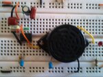
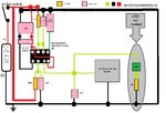
Here are two pictures of the breadboard I used and a horrible block diagram of the wiring (more confusing that a schematic maybe!):

BLIP 555 breadboard 1 breadboard.JPG BLIP 555 breadboard 2 block diagram wiring.JPG

I don't know if they are of any help or not, I hope so. Also, here's a video of it working (it's a SE555P on a 4.76V supply)

As we discussed, anti-spark switches do not look 555 start-up friendly. I believe the circuit needs an absence of a positive voltage before turn-on for the 555 internals to sense the levels they need to function correctly - that looks impossible with an anti-spark switch design of a permanent 4.2 to 42V on the circuit and either "nothingness" or 0V appearing in the circuit when switched on... Not sure about that, but for example to me nothing and zero look the same level, I guess for the 555 and the capacitors too.

Maybe someone else with experience of 0V switches can suggest a sensible workaround - I can't think of a solution of where it may be safe to tap into a useful signal without disturbing the longboard's correct operation without knowing the longboard in detail which clearly I do not.
 
The block diagram is exactly my circuit. My BEEP sound is so low that flying of mosquito is louder, and I tried two of a kind.
I'll try later to connect a Led and see if it's lighted.
 
  • Like
Reactions: d123

    d123

    Points: 2
    Helpful Answer Positive Rating
Status
Not open for further replies.

Part and Inventory Search

Welcome to EDABoard.com

Sponsor

Back
Top