Continue to Site

Welcome to EDAboard.com

Welcome to our site! EDAboard.com is an international Electronics Discussion Forum focused on EDA software, circuits, schematics, books, theory, papers, asic, pld, 8051, DSP, Network, RF, Analog Design, PCB, Service Manuals... and a whole lot more! To participate you need to register. Registration is free. Click here to register now.

[SOLVED] Triangle wave generator makes an ugly triangle wave

Status
Not open for further replies.

Plecto

Full Member level 5
Joined
Jan 4, 2012
Messages
315
Helped
1
Reputation
2
Reaction score
1
Trophy points
1,298
Activity points
4,979
As a part of a work related project I have to use a triangle wave generator as a part of a class D amplifier. The generator works, but the quality of the triangle wave causes distortion. I'm having a hard time figuring out what's causing this and I'm wondering if anyone could give me some tips.

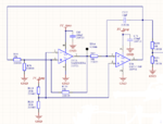
Circuit:
Capture.PNG

Note: A 100nF capacitor has been put in parallel with R120. Also, R79 is unpopulated.

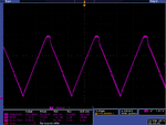
Triangle wave:
tek00094.png
 

can you attach the capture of square waveform at TP14?
 

Are you sure this operational amplifier can swing the output rail-to-rail ?
 

It looks like the top level is in beginning saturation. I also guess that you see capacitive crosstalk shortly after the reversal points. The small oscillations in the middle of both ramps however needs explanation.

Can we exclude that it's somehow a probing effect? How did you connect the oscilloscope? Or does the triangle drive another circuit, e.g. a comparator? If so, disconnect it for the time being.
 

Hi,

The problem with a triangle shape is, that it has a lot of overtones.
Overtones without a limit in frequency. Infinite frequency.

But we have limited frequency...thus we can't have a perfect triangle.
You need a very high frequency Opamp to get a good triangle shape.

Here a link to an internet page where one can see how a triangle is made with sinewaves according fourier series.
https://mathworld.wolfram.com/FourierSeries.html

Klaus
 

According to the waveform the distortion appears at the maximum peak whereas the minimum peak seems correct, so the circuit bandwidth sounds as not being the main issue on this case in particular; perhaps the signal amplitude is to high, reaching the upper allowed limit of input or output of the OpAmp, since it is too close of VDD.
 

Maybe you are trying too hard. For a simple foolproof
triangle-ish modulator input I like switched-RC. Not
dead linear but requires only two comparators and a
SR FF, and a fat inverter to drive the resistor. 1/3
and 2/3 VDD trip points for the comparators (ala LM555)
again dead simple to make.

So what if the triangle wave isn't textbook perfect?
Is there any observable downside, or just "not perfect"?
 

The amplitude was set too high. Increasing R118 to 13k fixed it :) Thank's for all the replies
 

Status
Not open for further replies.

Similar threads

Part and Inventory Search

Welcome to EDABoard.com

Sponsor

Back
Top