promach
Advanced Member level 4
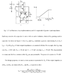
could I see intuitively how the Zin equation comes about without deriving it step-by step ?
Someone told me the following but I am still confused
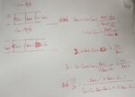
How do I derive the equation "Just 1/(gm1rout1gm2). I.e. 1/total_gm" ?


Someone told me the following but I am still confused
The first gm stage plus CL forms an integrator. What is it integrating? The voltage at node X. The second gm stage completes a feedback loop which tries to keep the voltage at node X held constant at the point where you get no output current from the first gm stage. If you inject a current into node X, the feedback loop will respond to adjust the voltage on CL until the 2nd gm stage absorbs all of that current. This gives you a low impedance at low frequencies. How low? Just 1/(gm1rout1gm2). I.e. 1/total_gm. What happens at high frequencies? CL becomes low impedance effectively removing the effect of the feedback loop. Now the impedance you see is high. How high? Ignoring capacitances associated with the gm stages, Rout2. So you have a low impedance at low frequencies that becomes high impedance at high frequencies. That is an inductor. For the two break frequencies think about it this way. At very low frequencies, Rout1 has a lower impedance than CL and it isn't until Rout1 = |1/(jwCL)| that you start to see appreciable effects from CL. That is just w = 1/(Rout1CL). At the high frequency end, you can solve for when the inductive part equals Rout2, or you can disconnect node X from all but the gm stages and realize that CL sees a resistance of 1/(gm2Rout2gm1) and so the pole frequency is 1/(gm2Rout2*gm1). Note that this analysis and the plot you show both ignore the effects of capacitances associated with the transistors in the gm stages. Those will be important at some point.
How do I derive the equation "Just 1/(gm1rout1gm2). I.e. 1/total_gm" ?

